Download
1 / 31
310 likes | 480 Views
Intrabeam Scattering, Impedance, and Instabilities in Ultimate Storage Rings. Karl Bane FLS2012 Workshop 7 March 2012. Outline of Talk. Longitudinal microwave instability --Coherent synchrotron radiation (CSR) --Impedance scaling for small angle transitions

E N D
Intrabeam Scattering, Impedance, and Instabilities in Ultimate Storage Rings Karl Bane FLS2012 Workshop 7 March 2012
Outline of Talk • Longitudinal microwave instability --Coherent synchrotron radiation (CSR) --Impedance scaling for small angle transitions --Impedance budget --Pseudo-Green function wake • Other instabilities • Intra-beam scattering (IBS) • Touschek lifetime • Conclusions As specific example illustrating the above topics I will use cases of PEP-X, a study effort of a group led by Y. Cai
Introduction • An “ultimate storage ring” is a term used to describe a ring with diffraction limited emittances at 1 angstrom wavelength • Two 4.5 GeV versions have been designed for the PEP tunnel: • A: 2010 (SLAC-PUB-13999), x= 165 pm, y= 8 pm, I= 1.5 A, lattice TME + DBA • “baseline” • B: 2012 (SLAC-PUB-14785), x= 12 pm, y= 12 pm, I= 0.2 A, lattice 7BA • “ultimate” • Since I for Design A is so much larger, will discuss instability calculations for A • (e.g. Boussard criterion for threshold to microwave instability: ) • But will apply IBS and Touschek calculations for (the recently developed) Case B.
Selected Parameters for PEP-X Note that the nominal horizontal emittance x0= 0/(1+), with the x-y coupling parameter
test v =c driving Microwave Instability Due to Shielded CSR (K. Bane, Y. Cai, G. Stupakov, PRST-AB, 2010) height 2h Wake of particles moving at speed c, on circle of radius , between two metallic plates located at y= h was found by J. Murphy, et al. For a bunch, the normalized threshold current S is a function of normalized shielding parameter , with
We have performed Vlasov-Fokker-Planck simulations (a la R. Warnock and J. Ellison, SLAC-PUB-8404, 2000) for the shielded CSR wake to find threshold as function of . Example simulation result, showing p/p0 vs. number of synchrotron periods Ns. This example is above threshold.
Result: For the CSR wake, threshold values of current S vs. shielding parameter . The dashed curve is Sth= 0.50 + 0.12 . For PEP-X, vacuum chamber is elliptical with axes (20.0, 12.5) mm and bending radius = 100.8 m => = 22.7 and Ith= 3.6 A, far above design I.
Impedance Scaling for Small Angle Tapers From “Impedance calculation for the NSLSII storage ring,” A. Blednykh • With the insertion gap becoming ever smaller, the insertion region becomes a dominating part of the ring impedance • Insertion transitions tend to be long, gradually tapered, and 3D => it is very challenging to obtain the wakefield for a short bunch • Impedance scaling of small angle tapers
Impedance Scaling for Small Angle Transitions (G. Stupakov, K. Bane, I. Zagorodnov, PRST-AB, 2011) • At high frequencies, envelope equation for fields satisfies parabolic equation • For small angle transitions, the parabolic equation is valid for all frequencies • As a consequence the wakes of such a transition is approx. related to that of the transition but scaled in the z direction by factor as: • Sketch of a small angle transition (left), and the scaled one with = ½ (right) • For 2D time-domain calculation this implies reduction in required computer resources of 3, for 3D of 4 = 1/2 full scale
We test the scaling using ECHO, I. Zagorodnov’s time-domain wakefield solving program. Longitudinal (left) and transverse (right) wake of Gaussian bunch passing through a 2D small-angle transition to a long central pipe and back again. The radius of the beam pipe is 48 mm, of the central pipe is 7.5 mm, the taper angle is 5.8 deg, and z= 0.5 mm. The full calculation is in blue, the scaled result in red; the nominal bunch shape is in black.
A 3D Example (b) (a) A 3D symmetric, small-angle transition (of which one taper is shown in cut-view) with a long interior pipe (a); the longitudinal (b) and dipole (c) wake. Exterior pipes are 30 mm x 30 mm (x by y), interior pipe is 30 mm x 15 mm, the taper angle is 3 deg, and z= 0.5 mm. The full calculation is in blue, the scaled result in red; the nominal bunch shape is in black. (c)
Longitudinal Impedance Calculations for PEP-X • For PEP-X, without an actual vacuum chamber design available, we developed a straw man design, inspired by objects in other machines, such as PEP-II • Sources include: RF cavities, BPM’s, wiggler transitions, undulator transitions, resistive wall, coherent synchrotron radiation (CSR) • For the microwave instability, generate: • (i) a pseudo-Green function wake representing the ring—to be used in simulations (z= .5 mm; nominal is 3 mm) and reaching to 60 mm behind the bunch • (ii) an impedance budget—to assess relative importance of contributors • People involved in 3D code development and impedance calculation include L.-Q. Lee, C.-K. Ng, L. Wang, L. Xiao
Selected PEP-X Impedance Sources RF cavity BPM Pair of wiggler transitions Pair of undulator transitions Selected impedance objects included in our straw man PEP-X design. Note: the fundamental mode fields are shown in the RF cavity.
Impedance Budget Impedance budget for PEP-X, giving the loss factor, and the effective resistance and inductance of the various objects in the ring. The results are at nominal bunch length z= 3 mm.
Pseudo-Green Function Wake Pseudo-Green function wake representing the PEP-X ring: wake of a z= .5 mm bunch Haissinski solution, giving the steady-state bunch shape. Bunch length is 25% above nominal length. (G. Stupakov) Front
Instabilities in PEP-X (Baseline, I= 1.5 A) G. Stupakov, L. Wang Microwave: Can cause p, z to increase, saw-tooth instability, heating. With PEP-X impedance we find 25% z increase (potential well distortion) but no threshold until I> 8 A Transverse Single Bunch: Can cause beam to be lost. When including only the resistive wall impedance (dominant in the insertion devices), the threshold is 1.5 times the nominal current. Other impedance objects will reduce this value. Since transverse resistive wall wake a-3, (a is aperture) this is a serious limitation to reducing the aperture of the insertions. Multibunch Transverse: Including only the resistive wall wake, which often dominates the multibunch transverse instability, the calculation yields a growth time of .14 ms, or 19 turns. Good feedback is needed. Fast Ion: Multi-particle tracking shows that the instability is strong, though with a compromise between vacuum level and bunch gapsize, the growth rate can be kept to a level that are manageable with feedback.
(Thanks to A. Xiao, M. Borland, K. Kubo) Intra-Beam Scattering (IBS) for Ultimate PEP-X IBS describes multiple Coulomb scattering that leads to an increase in all bunch dimensions and in energy spread Assume coupling dominated (y is negligible and can be ignored): y= x Steady-state IBS emittance and energy spread: where sum emittance = x+y, and x = /(1+); subscript 0 indicates zero current values; x*= x/(1+x/y) Local IBS growth rates (1/Tx), (1/Tp), are functions of beam and lattice parameters; their average around the ring are the growth rates 1/Tx, 1/Tp We follow the Bjorken-Mtingwa (BM) formulation of 1/Tx, 1/Tp; solution involves (i) an integration at every lattice element, (ii) averaging around the ring, (iii) solving the above two equations simultaneously Due to small impact parameter events, the tails of distributions are not Gaussian; Coulomb log reflects this; for PEP-X, (log) 11
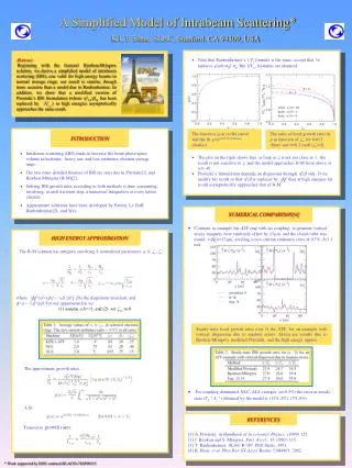
Simplified Model of IBS (K. Bane, EPAC02) Longitudinal growth rate: Transverse growth rate: Valid for a, b<< 1, “high energy approximation” = <(1/Tp)>
Solution for PEP-X • For PEP-X consider round beam, = 1 • Table. Steady-state beam properties in PEP-X at zero current and nominal current. Results were obtained using the Bjorken-Mtingwa (B-M) formalism. • Note: almost no growth in p or z • In nominal configuration Tx-1= 52. s-1, Tp-1= 7.4 s-1 (simplified model gets • Tx-1= 53.7 s-1, Tp-1= 8.9 s-1 )
Checked results with SAD, an optics program that treats coupling without simplifying assumptions (i.e. solves for true emittance invariants), and that can also solve the B-M IBS equations. (K. Kubo) • Procedure: • 1 In dispersive-free region of PEP-X: • (i) adjust quad strengths to bring tunes close together, • (ii) randomly rotate 400 quads by small amount, with scale factor adjusted to give x y • 2 Perform IBS calculations • 3 Repeat for 10 seeds • Result: steady-state x y 11 pm, with variation of few percent for the different seeds
Accumulated IBS Growth Rates Accumulated growth rates in p, x; Hx optics function
Correlation between Hxand (1/Tp) in PEP-X Arc Straight Tp1 [s1] 80Hx[mm] Hxand (1/Tp) over one arc and one straight of PEP-X Note the anti-correlation of the two functions in arc With no correlation but “same” lattice parameters, 1/Tx would be twice as large
Emittance Dependence on Current • With Tp1 small, from simplified model can show that steady-state emittances can be approximated by • with IA= 17 kA and a constant analytical formula Steady-state emittances as function of bunch current in PEP-X. The dashed curve gives the analytical approximation.
Dependence on Energy (M. Borland) Emittancex= y vs. energy for a round beam at nominal current (black) and at zero current (red).
Touschek Lifetime for Ultimate PEP-X • Touschek effect concerns large, single Coulomb scattering events where energy transfer from transverse to longitudinal leads to immediate particle loss • Number of particles in bunch decays as: • Can’t use usual (flat beam) formula of Brueck • Use general formula due to Piwinski. Inverse of Touschek lifetime: • B1~ x,y/x,y=> where x,y is large, 1/T is small because of exp(B1) factor in integral. This factor is also reason 1/T becomes small at very small x,y.
Momentum Acceptance in PEP-X (Min-Huey Wang) Momentum acceptance due to linear optics for PEP-X. The average value is m= 2.8%.
Touschek Lifetime Results • Result for the IBS-determined steady-state beam sizes is: T= 11 hrs • Accumulation around the ring of the Touschek growth rate in PEP-X. The growth is significant only in the arcs, where x,yare small.
Dependence on Momentum Acceptance Touschek lifetime T vs. (global) momentum acceptance parameter, m (blue symbols). The dashed curve gives the fit: T= 0.088(m/0.01)5 hrs.
Touschek Lifetime vsEmittance As the length of wiggler Lw increases, the emittance decreases. In PEP-X design Lw= 90 m, xnom= 11 pm (including IBS), Tnom= 11 hrs Emittancex ( y) and Touschek lifetime Tvs wiggler length Lw (left plot), and Tvsx (right). These are results of self-consistent calculations including IBS.
Conclusions • In ultimate storage rings, such as the latest version of PEP-X, impedance effects tend not to be important since the current is quite low (200 mA) • IBS sets the limit of current that can be stored in an ultimate ring. In PEP-X with round beams, IBS doubles the emittance to 11 pm at the design current of 200 mA • The Touschek lifetime in ultimate PEP-X is quite large, 11 hrs, but it is a very sensitive function of the momentum acceptance • How to run a machine with a round beam needs serious study. E.g. using vertical dispersion may be preferable to coupling. The choice will affect the IBS and Touschek effect • In the higher current version of PEP-X (baseline, 2010, I= 1.5 mA), the transverse single and multi-bunch instabilities can become an issue, with the small-gap insertion devices becoming dominant contributors to the (transverse) ring impedance