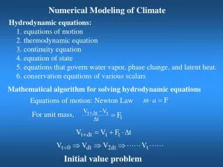
Download
1 / 44
440 likes | 460 Views
Changcheng Sept.6,2008. Field work and Numerical modeling Summary. Outline. Fieldwork Study area Geological map and structural data Geological deformation history Future work Numerical modeling of clasts Background clast modeling Behavior of single clast

E N D
Changcheng Sept.6,2008 Field work and Numerical modeling Summary
Outline Fieldwork Study area Geological map and structural data Geological deformation history Future work Numerical modeling of clasts Background clast modeling Behavior of single clast Problems with application of clast modeling My modeling and its application Conflict: data from field and modeling; possibility Future study
Fieldwork: Study area (Modified from Tollo et al., 2004, reference therein)
Fieldwork: Study area (Modified from Tollo et al., 2004, reference therein)
Simplified Geological map (modified from Ames et.al, 2005)
Structural data:Foliation Varies with location Approaching GF: Trend to parallel to GF Away from GF: striking EW or NS Two types of fliations
Foliation1: Transpositioning foliation 1 Defined by isoclinal fold axial plane F1 fold S1
Transpositioning foliation1 Folded by chevron fold Chevron fold postdate transpositioning foliation1 Schevron
Foliation2: Transpositioning foliation 2 Defined by chevron fold axial plane Transpositioning foliation 2 F3 (explain later) Schenvron
Chevron fold axial plane orientation Orientation doesn’t change much All striking NEE Parallel to GF Most dipping toward SE, minor dipping NW
Fanned chevron fold axial planes Opposite dipping fold axial planes In case of perfect flat layer was folded: Fold axes parallel everywhere Fold axis Fold axial plane (From “Structural analysis of metamorphic tectonites” p.189)
Chevron fold axial plane orientation Folded by an open fold
Chevron fold axial plane orientation Folded by an open fold
Chevron fold Overprinted by open fold Open fold
Chevron fold axis Not parallel NE or SW Some SE
Chevron fold axis and Transpositioning foliation 1 Transpositoning foliation 1 FA Relation: When this foliation strikes NNE, FA trends NE; when foliation EW, FA trends SW
Chevron fold axis plot Chevron fold
Transpositioning foliation 1 Not chevron fold What control the orientation of this foliation?
F2 on aerophoto S3 S3 S3 S3 S1 S1
F3 overprint F2 Chevron fold: F3 F3 Fold axis orientation depends on F2 F3: Syntectonic with GF mynolite zone
Other deformation fabrics Boudinage & Boudine neck fold Chevron fold with material melt Dyke and folding
Boudinage & Boudine neck fold Boudinage & Boudine neck fold
Dyke and folding Intruded predate or at early stage of D1 At very late stage of D1 or even after D1 S1
Deformation history Summery D1: Transpositioning foliation 1, isoclinal folds, Boudinage, Boudine neck fold D2: Regional fold. No foliations was developed. Controlling the orientation of foliation when it is away from GF D3: Chevron fold. GF mylonite zone. Intersection lineation, fold axis lineation D4: open fold.
Future work about field work Any potential to constrain the time of 4 deformation phases Numerical modeling of D3 : shear zone modeling PT Relates to regional background(deformation event, tectonic environment)
Clasts modeling Background Single clast behavior Problems with application of clast modeling My modeling of a population of clast Rf/phi plot, conflict Future work
Clast-matrix system modeling background Rheological property, bulk deformation kinematics, strain, shape preferred orientation Application: Conglomerates, igneous rocks containing xenolith, porphyroblast-bearing metamorphic rock, mylonite zone Modeling: analogue modeling, numerical modeling. single clast behavior, a population of clast behavior. Rigid clast with (no) slip interface, deformable clast. My modeling: Rigid clast in newtonian fluid with no slip interface (Porphyroclast in mylonite zone, Kinematics)
Rigid clast in newtonian fluid with no slip interface Behavior according to Jeffery’s theory (1922): tested by many experiments Behavior governed by (Jeffery’s equation): matrix flow (bulk deformation kinematics), clast shape, and clast instantaneous orientation Analytical solution of Jeffery’s equation: Monoclinic flow and spheroidal clast (clast with symmetric axis)
Single clast behavior Spheroidal clasts Simple shear Pure shear General shear (monoclinic shear) Ellipsoidal clasts (No symmetrical axis): unregular behavior, too complicated, no stable orientation.
Spheroidal calst in monoclinic general shear Critial aspect ratio: Rc=2.2 untable clasts Rc*Rc-1 Wk= Rc*Rc+1 long axis Aspect ratio Rf= short axis Proved in theory in case of spheroidal Clast with symmetrical axis in vorticity Normal section (2D).
Rf/phi plot application in shear zone Based on spheroidal clast behavior (From Jessup et al., JSG, V.92, p411-421) (Law et al., JGS, London, V.161, p305-320)
Wk, Wks, and bulk deformation kinematics Wk: Representation of contribution of simple shear and pure shear component Wk: not equal Wks Wks ignore pure shear component that is along vorticity vector Rf/phi is for Wks not Wk Simple shear Wk=1 Pure shear Wk=0 General shear 0<Wk<1
Problems with Rf/phi clast plot application Only a population of ellipsoidal clast with the same aspect ratio is numerically modeled: don’t support Rf/phi method Analogue experiment: aspect ratio<1.3, can be regarded as sphesoidal clast: support Rf/phi method Isn’t comparable to field data Wk is incorrectly calculated
My modeling of a population of ellipsoidal rigid clasts in monoclinic shear 300 Randomly distributed orientation clasts various aspect axis ratio Specify bulk deformation kinematics (Give Wk), model clast rotation Study on Vorticity normal section Test Rf/phi plot method
My modeling result about Rf/phi plot in terms of monoclinic shear Rf/phi can be applies to ellipsoidal clasts when finite strain is high enough. The finite strain needed is too high for nature shear zone, and Wks is under estimated by Rf/phi plot. Some of field data isn’t comparable to the plot Not likely be able to apply to triclinic shear zone.
Ellipsoidal clast Rf/phi plot: an example Preset in modeling:Wk=0.227 -> Wks=0.5 Rc=1.7 Calculation by Rf/phi plot: (Rc*Rc-1)/(Rc*Rc+1)=0.486=Wks !=Wk Wks instead of Wk can be determined by Rf/phi plot providing finite strain is high enough
Ellipsoidal clast, Rf/phi plot, and Finite strain in monoclinic shear Preset in modeling:Wks=0.857 Finite strain not high enough Calculated Wks =0.77 Finite strain high enough Calculated Wks =0.86
Field data modeling conflict Preferred orientation from modeling of rigid clast without interface slip. Data collected in field. Not rigid clast without interface slip?
Data collected in field conflict with modeling but Wk calculation is based on modeling My modeling (From Jessup et al., JSG, V.92, p411-421) (Law et al., JGS, London, V.161, p305-320)
Possibility of conflict Strain localization (Wk varies with space) Strain not high enough Non-steadystate deformation (Wk varies with time) No all clast behave according to Jeffery’s theory: Interface-slip? Not Newtonian flow?
Future work about clast modeling Get my own clast data (mylonite thin sections) Strain localization test both numerically and thin section study (Not likely be the reason to conflict) Thin section study: Jeffery’s theory clast and other clasts in thin section Non-steadystate deformation modeling
Questions and suggestions? Thanks!