Download
1 / 43
430 likes | 437 Views
This senior thesis presentation analyzes the structural redesign proposal for Granby Tower in Norfolk, Virginia, exploring goals, gravity system, construction delays, and cost analysis.

E N D
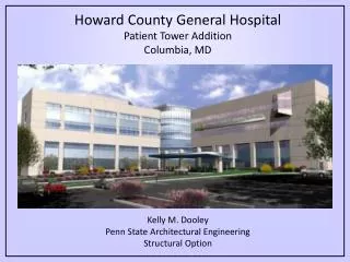
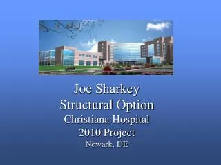
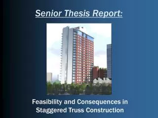
tom yost BAE/MAE - structural option granby tower norfolk, virginia senior thesis presentation 14 april 2008
granby tower norfolk, virginia • building overview • proposal • goals • depth • gravity system redesign • breadth study • reduction in construction schedule • cost analysis • conclusion/recommendation
granby tower norfolk, virginia • 34 story post-modern mixed-use high-rise • 302 luxury condominiums • offices • shops • parking garage • square footage: 781,479 • site area: 2.32 acres • project cost: $181,000,000 • original project duration: Sept 2005 – Nov 2009 • Construction delayed since 18 September 2007
granby tower norfolk, virginia • location: 515 Granby Street • views of downtown Norfolk and Elizabeth River
granby tower norfolk, virginia • owner: Marathon Development / 515 Granby, LLC. • architect: Humphreys & Partners Architects, LP. • structural:Abiouness, Cross and Bradshaw, Inc. • project management: Turner Construction Co.
granby tower norfolk, virginia • existing foundation • 12” & 14” square, precast, pre-stressed conc piles • over 1200 piles throughout site • 255 – 14”SPPC piles with 10’ thick pile cap support shear wall core. • 156 tension piles
granby tower norfolk, virginia • existing floor system • 8” two-way post-tensioned flat plate • f’c = 5000 psi • ½”ø 7-wire, low relaxation strand • 1 day to post-tensioning per floor • 46 days shoring time • existing columns • cast-in-place square or rectangular columns • f’c = 6500 psi (base to level 6) • f’c = 5000 psi (level 7 and up)
granby tower norfolk, virginia • existing lateral system • ordinary reinforced concrete shear wall cores • base to level 6: 24” thick, f’c = 8000 psi • level 7 to level 23: 14” thick, f’c = 6000 psi • level 24 to level 34: 14” thick, f’c = 5000 psi • typical boundary element reinforcement: (10) #10
granby tower norfolk, virginia • construction delay • construction stopped 18 september 2007 • initial investor reneged loan commitment • less stringent lending laws led to abundance of sub-prime lending and resulted in foreclosures • economic recession due to housing slump • tightening credit requirements • need new investor to secure bank loan • need 70% of units sold for loan • Almost 50% of units sold • Remaining units require “jumbo” mortgage
proposal summary • gravity system redesign • Girder-Slab system • keep original design for lower 7 floors • allows time to finish redesign • minimal disturbance to foundations • original system best for parking garage • allows for steel and precast procurement • check shear wall reinforcement
goals • prove applicability of Girder-Slab system • keep minimum floor depth • realize benefits of steel construction • decrease construction schedule • catch up on delayed schedule • save on construction loans • save money
girder-slab system • composite steel and pre-cast system • open-web dissymmetric beams • benefits • shallow floor depth • speed of steel construction • no shoring with precast • lighter system than existing • limitations • max D-Beam span 18’ • regular bays
possible column layouts • column layout 1
possible column layouts • column layout 1 • bay size: 16’ x 30’ • pros: • minimal architectural intrusion • simply supported condition for all planks • cons: • two-way transfer slab at 7th level • additional transfer level at 25th level • increased building height • increased cost
possible column layouts • column layout 2
possible column layouts • column layout 2 • bay size: varying sizes • pros: • one-way transfer girders (instead of two-way) • simply supported condition for all planks • maintain column placement as building tapers • cons: • additional columns • increased architectural intrusion • increased building height • increased cost
possible column layouts • column layout 3
possible column layouts • column layout 3 • bay size: original bays • pros: • no transfer girders required • no increase in building height • no architectural intrusion • cons: • costly moment connections • additional floor depth required at cantilevers • column layout 3 – best option
cantilevers • levels 8 through 24
cantilevers • moment connection • economy in mind – no field welds
cantilevers • cantilevered beam between A1 & A2
cantilevers • cantilever A1 & B1 • angle welded to web for low profile
lateral analysis • ETABS • considered additional wind • cases from ASCE 7-05, • figure 6-9 • assigned piers • pier forces checked with • PCAColumn • boundary elements okay
construction schedule • existing schedule • duration: 353 days (level 8 to substantial completion) • typical floor duration: 192 days • 46 days shoring time required • 8 day floor schedule • proposed schedule • duration: 266 days (87 day reduction) • typical floor duration: 129 days • girder-slab erection pace: 5000 SF/day • 5 day floor schedule • change in crew sizes • shear walls: 8 days per two levels (4 days/level)
cost analysis • existing system • RS Means • local pricing • proposed system • Girder-Slab Technologies • RS Means
cost analysis • savings due to scheduling • general conditions • 4 month savings = $1.2M • construction loan • 4 months of $140M loan at 12% per year = $5.6M (at end of project) • overall system cost
were goals met? • Girder-Slab system feasible redesign? • decrease construction schedule? • save money?
recommendation • gravity system redesign • girder-slab applicable for upper 27 floors • allows for easy integration • minimal architectural intrusion • construction schedule • reduced schedule by 87 days • time savings will aid in condo sales • cost analysis • saved owner $1.95M in construction costs • girder-slab system recommended for redesign
acknowledgements I would like to thank the following people for all of their help during this thesis research process: Industry Professionals: David Wysong – Turner Construction Daniel Fisher – Girder-Slab Technologies Elias Logothetis Professors: Dr. Andres Lepage – Penn State University Colleagues: Nasser Abdul-Azim Mohammed Jawad Hassan Marafi Brian Heart “Captain” Kirk Stauffer Phil “Fillet Weld” Frederick Allen Sky Walker And most of all, my family for supporting me and encouraging me to follow my dreams.
special connections • girder-slab tree connection
special connections • embedded plate at shear walls