Tower 333 Structural Redesign: Core-Only Solution Proposal
430 likes | 508 Views
This senior thesis project outlines a redesign proposal for Tower 333, aiming to eliminate moment frames, improve lateral system performance, and optimize construction costs and schedules. The focus is on a core-only structural solution. Through detailed analysis and design considerations, the proposal presents a viable economic alternative for the building. The proposal also addresses peer review requirements and seismic performance objectives.

Tower 333 Structural Redesign: Core-Only Solution Proposal
E N D
Presentation Transcript
PAUL PARFITT BAE/MAE Structural Option Senior Thesis Tower 333 May 4th 2007
Tower 333 • Introduction • Proposal • Lateral System Redesign • Elimination of Moment Frames • Core-Only Solution • Cost Analysis & Schedule Reduction • Building Envelope Performance & Quality Control • Conclusion/Recomendation
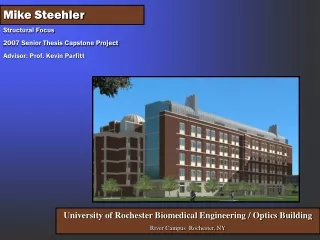
Tower 333 • Owner: Hines Development • Structural: Magnusson Klemencic Associates • Architect: LMN Architects • Location: Bellevue Washington • Height: 267 feet • # Of Stories: 18 above grade, 8 below grade • Floor height : 13’-10” Parking levels: 9’-10” • Floor Plate: 22,000 ft2 • Building Area: 594,000 ft2 • Tower crane collapsed Nov. 16th with one fatality • Uses existing foundation from previously abandoned project • Previous owner went bankrupt
Existing Structure Pre-existing Foundation: • Columns: spread footings • Core: mat slab • Sub levels 8-5 previously finished when owner went bankrupt Foundation Designed by MKA: • Sits on existing foundation from previously abandoned project • Columns sit on spread footings (reinforced where needed) • Core sits on mat foundation additional 24” concrete added to mat slab.
Existing Structure Gravity System: • 2-1/2” concrete slab on a 3” deep composite metal deck f’c=4,000psi. • Typical bay of upper office floors supported by 42’ long W18x40 composite beams and 30’ long W18x97 composite girders Superimposed Dead Loads: Mechanical/Electrical: 5 PSF Partitions: 20 PSF Misc. : 5 PSF Live Loads: 50psf
Existing Structure Lateral System: • Dual, concrete core & special perimeter steel moment frames • Concrete Core: f’c=9,000psi • By ASCE7-05, steel moment frames are designed for 25% of base shear • MKA design modeled in ETABS. Due to relative stiffness of moment frames, only 10% of base shear resisted in frames
Proposal Goals: • Eliminate special moment frames • Utilize pre-existing core • Develop into core-only lateral force resisting system • Reduce erection time • Save money in material costs • Reduce labor costs • Determine if proposed design is viable economic alternative
Proposal Things to Consider: • Peer Review criteria due to core-only system • Undersized core due to utilization of previous foundation • Torsion imposed on building • Story drift • Maximum building displacement • Shear capacity of coupling beams • Bending & shear capacity of piers
Lateral System Redesign Peer Review: • Peer review required by IBC 2003 for buildings 160 feet or higher without dual lateral system • Peer review provides an objective and technical review of the structure under seismic conditions
Lateral System Redesign Redesign takes into account procedures set by LA’s & San Francisco’s Tall Buildings Code Tower 333 is Performance Based Design
Lateral System Redesign Performance Operational Collapse Prevention ImmediateOccupancy Life Safe Frequent(25 yrs) Unacceptable Performance Occasional(75 yrs) Earthquake Frequency (ReturnPeriod) Basic Objective (CODE) Rare500 yrs Essential/Hazardous Objective Safety Critical Objective MaximumConsidered (2500) Source: Vision 2000, FEMA-349
Lateral System Redesign Key Concepts: • Stringent peer review criteria • Eliminate moment frames. • Core-only alternative. • Plastic hinges at coupling beam connections critical to design. • Protects piers at base from significant yielding • Design coupling beams as flexure critical not shear critical
Lateral System Redesign Typical Floor Framing Plan
Lateral System Redesign • Trial size of 30” thick walls determined • Controlling case: Spectral Force in Y-direction (North-South) • ETABS analysis run on multiple design alterations Core Design Analysis Results From Critical (N-S) Directional Dynamic Loading
Lateral System Redesign Floor 18 Floor 14 Floor 7 Floor 1
Lateral System Redesign d1 d2 Torsion Multiplier & Eccentricity Ratio Ax Max = 1.71 Ecc. Ratio = .086
Lateral System Redesign Coupling Beams Concrete Piers
Lateral System Redesign Design of coupling beams: Beams in East-West direction utilize horizontal reinforcing Beams in North-South direction utilize diagonal reinforcing
Lateral System Redesign Pier Design: @ Floor 1 ρg = 1.6% Pier Design: @ Floor 9 ρg = 0.3%
Lateral System Redesign Performance Operational Collapse Prevention ImmediateOccupancy Life Safe Frequent(25 yrs) Unacceptable Performance Occasional(75 yrs) Earthquake Frequency (ReturnPeriod) Basic Objective (CODE) Rare500 yrs TOWER 333 Essential/Hazardous Objective MaximumConsidered (2500) Source: Vision 2000, FEMA-349
Lateral System Redesign Proposed New Lateral System: Floors P-8 through Mezzanine: Two symmetrical “C” shaped core walls 36” thick all levels Floors 1 through 18: Four symmetrical “L” shaped core walls 36” thick @ fl. 1-6 30” thick @ fl. 7-13 24” thick @ fl. 14-18 60” deep coupling beams in (North-South) direction 45” deep coupling beams in (East-West) direction Max building disp.: 33” = 1.03% of building height Max story drift: 1.3% < 1.5%
Cost Analysis & Schedule Reduction Goals : • Core-only lateral system that performs well under seismic conditions • Provide a system that is cheaper • Reduce building erection time Considerations: • Cost of shop labor/materials • Reduced erection time • Revenue from early finish date
Cost Analysis & Schedule Reduction Material Cost: • Eliminated two sets of 2’ thick x 6’ x 13’-10” volume of concrete from each upper floor Savings of 234 CY concrete = $152,000 • Concrete added to thickened core: • Sublevel 8 through Mezzanine:36.4 CY/floor • Floor 1 through Floor 6:50.4 CY/floor • Floor 7 through Floor 13:25 CY/floorTotal cost of additional concrete: $523,000 • Fire rated drywall for exposed core: • Amount of drywall needed: 6,408 ft2 • Cost of added fire rated drywall: $23,700
Cost Analysis & Schedule Reduction Moment Frames: Contacted Steel Fabricator for representative costs for Seattle Area • Shop costs of creating a moment connection end was $910/end. • Approximately 400 ends in perimeter moment frames • savings of these connections totaled $364,000. • Cost of doubler-plate $380 • 280 doubler-plate/stiffeners locations located in the moment frames • savings of $106,400 • Saving 682,000 lbs of steel = $785,156 • Total cost savings in elimination of moment frames: $1,255,155 (This figured does not include savings in erection labor which equated to 4,000 hours of field labor.)
Cost Analysis & Schedule Reduction Erection Time: • One E-6 crew of 16 workers • One E-9 crew of 16 workers • 256 man hours per day • 4,000 labor hrs/256 hrs/day = 16 days saved in labor • 7.6% reduction over 210 day steel erection schedule
Cost Analysis & Schedule Reduction 11 days saved in erection schedule • E-6 crew costing $8,277/day • E-9 crew costing $8,468/day • Over 11 days = $221,581
Cost Analysis & Schedule Reduction • Modified building schedule • Turn over building 1 week early • Rent: $25/ft = $190,400 revenue • 951 parking stalls @ $47/week = $44,700 • Total rental revenue $235,100 (Does not include additional savings in administrative and finance costs)
Cost Analysis & Schedule Reduction Summary of Building Cost for Core-Only Lateral System: • Concrete saved: --------------------------------------------- (+) $152,000 • Concrete added: -------------------------------------------- (-) $523,000 • Fire Rated Walls: ------------------------------------------- (-) $23,700 • Steel shop production: ------------------------------------ (+) $470,400 • Steel material: ---------------------------------------------- (+) $785,156 • Labor/Erection: --------------------------------------------- (+) $221,900 • Rent Revenue: ----------------------------------------------- (+) $190,400 • Parking Revenue: ------------------------------------------- (+) $44,700 • Total dollars saved with proposed core-only design: (+) $1,318,156
Building Envelope Performance &Quality Control Purpose of Building Envelope: • Prevent air & water leakage into building Poor performance: • Deterioration of polymer sealants • Deterioration of metals • Potential mold growth • Very costly to repair post construction Common Industry Assumption: Better design of specifications & design of building envelope = better performance Reality: Communication & Implementation is the primary problem
Building Envelope Performance &Quality Control • Solution: • Incorporate 3rd party building envelope consultant early in design phase • Continuous involvement good communication and implementation • Provides field tests & inspections • Two Kinds of Tests: • Mock-up test • In field test • Both follow: • ASTM E331 • AAMA 501.1-05 Static Pressure Field TestPhoto courtesy of SGH
Building Envelope Performance &Quality Control • ASTM 331“Uniform Static Air Pressure Difference”: • 2.86 lbs/ft2 • 5 gal/ft2/hr • Not accurate for wind driven rain • AAMA 501.1-05 “Dynamic Pressure” : • Mechanical wind machine • 5gal/ft2/hr • Test to run no less than 15 mins • Water penetration: ½ oz. or more through envelope in 15 minutes intervals Dynamic Pressure Test With Turbo Prop Engine
Building Envelope Performance &Quality Control • Quality assurance summary: • Quality is not just in specs and design • Communication & implementation is key • Hire 3rd party building technology consultant • Allows for better communication and implementation • Provide random field tests & inspections to ensure quality product. Static Pressure Field TestPhoto Courtesy of SGH
Conclusion • Was proposed design feasible? • Met all performance criteria • Max story drift 1.3% • Developed plastic hinges in coupling beams • Limit yielding in piers • Was proposed design economical? • Cheaper structure to build • Quicker erection time • Increased revenue due to early finish date
Conclusion Findings: • Proposed core-only design feasible & economical alternative to existing structure • Proper specs and design of envelope will not always prevent curtain wall problems Recommendation: • Recommend that proposed design be implemented • Recommend that 3rd party consultant be hired for quality assurance of building envelope erection
Acknowledgments Thanks to all the organizations that assisted: Hines Development Magnusson Klemencic Associates LMN Architects Simpson Gumpertz & Heger Wiss Janney Elstner Associates Penn State University: Dr. Andres Lepage Andreas Phelps The rest of the AE faculty & staff Special thanks to my family & fellow 5th year AE’s