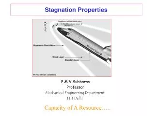
Stagnation Properties
Chapter 17 Compressible Flow Study Guide in PowerPoint to accompany Thermodynamics: An Engineering Approach , 5th edition by Yunus A. Çengel and Michael A. Boles. Stagnation Properties

Stagnation Properties
E N D
Presentation Transcript
Chapter 17Compressible FlowStudy Guide in PowerPointto accompanyThermodynamics: An Engineering Approach, 5th editionby Yunus A. Çengel and Michael A. Boles
Stagnation Properties Consider a fluid flowing into a diffuser at a velocity , temperature T, pressure P, and enthalpy h, etc. Here the ordinary properties T, P, h, etc. are called the static properties; that is, they are measured relative to the flow at the flow velocity. The diffuser is sufficiently long and the exit area is sufficiently large that the fluid is brought to rest (zero velocity) at the diffuser exit while no work or heat transfer is done. The resulting state is called the stagnation state. We apply the first law per unit mass for one entrance, one exit, and neglect the potential energies. Let the inlet state be unsubscripted and the exit or stagnation state have the subscript o.
Since the exit velocity, work, and heat transfer are zero, The term ho is called the stagnation enthalpy (some authors call this the total enthalpy). It is the enthalpy the fluid attains when brought to rest adiabatically while no work is done. If, in addition, the process is also reversible, the process is isentropic, and the inlet and exit entropies are equal. The stagnation enthalpy and entropy define the stagnation state and the isentropic stagnation pressure, Po. The actual stagnation pressure for irreversible flows will be somewhat less than the isentropic stagnation pressure as shown below.
Example 17-1 Steam at 400oC, 1.0 MPa, and 300 m/s flows through a pipe. Find the properties of the steam at the stagnation state. At T = 400oC and P = 1.0 MPa, h = 3264.5 kJ/kg s = 7.4670 kJ/kgK
Then and
We can find Po by trial and error (or try the EES solution for problem 3-27 in the text). The resulting stagnation properties are Ideal Gas Result Rewrite the equation defining the stagnation enthalpy as For ideal gases with constant specific heats, the enthalpy difference becomes
where To is defined as the stagnation temperature. For the isentropic process, the stagnation pressure can be determined from or Using variable specific heat data
Example 17-2 An aircraft flies in air at 5000 m with a velocity of 250 m/s. At 5000 m, air has a temperature of 255.7 K and a pressure of 54.05 kPa. Find To and Po.
Conservation of Energy for Control Volumes Using Stagnation Properties The steady-flow conservation of energy for the above figure is Since
For no heat transfer, one entrance, one exit, this reduces to If we neglect the change in potential energy, this becomes For ideal gases with constant specific heats we write this as Conservation of Energy for a Nozzle We assume steady-flow, no heat transfer, no work, one entrance, and one exit and neglect elevation changes; then the conservation of energy becomes
But Then Thus the stagnation enthalpy remains constant throughout the nozzle. At any cross section in the nozzle, the stagnation enthalpy is the same as that at the entrance. For ideal gases this last result becomes Thus the stagnation temperature remains constant through out the nozzle. At any cross section in the nozzle, the stagnation temperature is the same as that at the entrance. Assuming an isentropic process for flow through the nozzle, we can write for the entrance and exit states
So we see that the stagnation pressure is also constant through out the nozzle for isentropic flow. Velocity of Sound and Mach Number We want to show that the stagnation properties are related to the Mach number M of the flow where and C is the speed of sound in the fluid. But first we need to define the speed of sound in the fluid. A pressure disturbance propagates through a compressible fluid with a velocity dependent upon the state of the fluid. The velocity with which this pressure wave moves through the fluid is called the velocity of sound, or the sonic velocity. Consider a small pressure wave caused by a small piston displacement in a tube filled with an ideal gas as shown below.
It is easier to work with a control volume moving with the wave front as shown below.
Apply the conservation of energy for steady-flow with no heat transfer, no work, and neglect the potential energies. Cancel terms and neglect ; we have Now, apply the conservation of mass or continuity equation to the control volume. Cancel terms and neglect the higher-order terms like . We have
Also, we consider the property relation Let's assume the process to be isentropic; then ds = 0 and Using the results of the first law From the continuity equation Now
Thus Since the process is assumed to be isentropic, the above becomes For a general thermodynamic substance, the results of Chapter 12 may be used to show that the speed of sound is determined from where k is the ratio of specific heats, k = CP/CV. Ideal Gas Result For ideal gases
Example 17-3 Find the speed of sound in air at an altitude of 5000 m. At 5000 m, T = 255.7 K.
Notice that the temperature used for the speed of sound is the static (normal) temperature. Example 17-4 Find the speed of sound in steam where the pressure is 1 MPa and the temperature is 350oC. At P = 1 MPa, T = 350oC, Here, we approximate the partial derivative by perturbating the pressure about 1 MPa. Consider using P±0.025 MPa at the entropy value s = 7.3011 kJ/kgK, to find the corresponding specific volumes.
What is the speed of sound for steam at 350oC assuming ideal-gas behavior? Assume k = 1.3, then Mach Number The Mach number M is defined as M <1 flow is subsonic M =1 flow is sonic M >1 flow is supersonic
Example 17-5 In the air and steam examples above, find the Mach number if the air velocity is 250 m/s and the steam velocity is 300 m/s. The flow parameters To/T, Po/P, o/, etc. are related to the flow Mach number. Let's consider ideal gases, then
but and so The pressure ratio is given by
We can show the density ratio to be See Table A-32 for the inverse of these values (P/Po, T/To, and /o) when k = 1.4. For the Mach number equal to 1, the sonic location, the static properties are denoted with a superscript “*”. This condition, when M = 1, is called the sonic condition. When M = 1 and k = 1.4, the static-to-stagnation ratios are
Effect of Area Changes on Flow Parameters Consider the isentropic steady flow of an ideal gas through the nozzle shown below. Air flows steadily through a varying-cross-sectional-area duct such as a nozzle at a flow rate of 3 kg/s. The air enters the duct at a low velocity at a pressure of 1500 kPa and a temperature of 1200 K and it expands in the duct to a pressure of 100 kPa. The duct is designed so that the flow process is isentropic. Determine the pressure, temperature, velocity, flow area, speed of sound, and Mach number at each point along the duct axis that corresponds to a pressure drop of 200 kPa. Since the inlet velocity is low, the stagnation properties equal the static properties.
Now we tabulate the results for the other 200 kPa increments in the pressure until we reach 100 kPa.
Summary of Results for Nozzle Problem Note that at P = 797.42 kPa, M = 1.000, and this state is the critical state.
Now let's see why these relations work this way. Consider the nozzle and control volume shown below. The first law for the control volume is The continuity equation for the control volume yields Also, we consider the property relation for an isentropic process
and the Mach Number relation Putting these four relations together yields Let’s consider the implications of this equation for both nozzles and diffusers. A nozzle is a device that increases fluid velocity while causing its pressure to drop; thus, d > 0, dP < 0. Nozzle Results
To accelerate subsonic flow, the nozzle flow area must first decrease in the flow direction. The flow area reaches a minimum at the point where the Mach number is unity. To continue to accelerate the flow to supersonic conditions, the flow area must increase. The minimum flow area is called the throat of the nozzle. We are most familiar with the shape of a subsonic nozzle. That is, the flow area in a subsonic nozzle decreases in the flow direction. A diffuser is a device that decreases fluid velocity while causing its pressure to rise; thus, d < 0, dP > 0. Diffuser Results
To diffuse supersonic flow, the diffuser flow area must first decrease in the flow direction. The flow area reaches a minimum at the point where the Mach number is unity. To continue to diffuse the flow to subsonic conditions, the flow area must increase. We are most familiar with the shape of a subsonic diffuser. That is the flow area in a subsonic diffuser increases in the flow direction. Equation of Mass Flow Rate through a Nozzle Let's obtain an expression for the flow rate through a converging nozzle at any location as a function of the pressure at that location. The mass flow rate is given by The velocity of the flow is related to the static and stagnation enthalpies.
and Write the mass flow rate as We note from the ideal-gas relations that
What pressure ratios make the mass flow rate zero? Do these values make sense? Now let's make a plot of mass flow rate versus the static-to-stagnation pressure ratio.
This plot shows there is a value of P/Po that makes the mass flow rate a maximum. To find that mass flow rate, we note The result is So the pressure ratio that makes the mass flow rate a maximum is the same pressure ratio at which the Mach number is unity at the flow cross-sectional area. This value of the pressure ratio is called the critical pressure ratio for nozzle flow. For pressure ratios less than the critical value, the nozzle is said to be choked. When the nozzle is choked, the mass flow rate is the maximum possible for the flow area, stagnation pressure, and stagnation temperature. Reducing the pressure ratio below the critical value will not increase the mass flow rate. What is the expression for mass flow rate when the nozzle is choked?
Using The mass flow rate becomes When the Mach number is unity, M = 1, A = A* Taking the ratio of the last two results gives the ratio of the area of the flow A at a given Mach number to the area where the Mach number is unity, A*.
Then From the above plot we note that for each A/A* there are two values of M: one for subsonic flow at that area ratio and one for supersonic flow at that area ratio. The area ratio is unity when the Mach number is equal to one.
Effect of Back Pressure on Flow through a Converging Nozzle Consider the converging nozzle shown below. The flow is supplied by a reservoir at pressure Pr and temperature Tr. The reservoir is large enough that the velocity in the reservoir is zero. Let's plot the ratio P/Po along the length of the nozzle, the mass flow rate through the nozzle, and the exit plane pressure Pe as the back pressure Pb is varied. Let's consider isentropic flow so that Po is constant throughout the nozzle.
Pb = Po, Pb /Po = 1. No flow occurs. Pe = Pb, Me=0. • Pb > P* or P*/Po < Pb /Po < 1. Flow begins to increase as the back pressure is lowered. Pe = Pb, Me < 1. • Pb = P* or P*/Po = Pb /Po < 1. Flow increases to the choked flow limit as the back pressure is lowered to the critical pressure. Pe = Pb, Me=1. • Pb < P* or Pb /Po < P*/Po < 1. Flow is still choked and does not increase as the back pressure is lowered below the critical pressure, pressure drop from Pe to Pb occurs outside the nozzle. Pe = P*, Me=1. • Pb = 0. Results are the same as for item 4. • Consider the converging-diverging nozzle shown below.
Let's plot the ratio P/Po and the Mach number along the length of the nozzle as the back pressure Pb is varied. Let's consider isentropic flow so that Po is constant throughout the nozzle. • PA = Po, or PA/Po = 1. No flow occurs. Pe = Pb, Me = 0. • Po > PB > PC > P* or P*/Po < PC/Po < PB/Po < 1. Flow begins to increase as the back pressure is lowered. The velocity increases in the converging section but M < 1 at the throat; thus, the diverging section acts as a diffuser with the velocity decreasing and pressure increasing. The flow remains subsonic through the nozzle. Pe = Pb and Me < 1. • Pb = PC = P* or P*/Po = Pb/Po = PC/Po and Pb is adjusted so that M=1 at the throat. Flow increases to its maximum value at choked conditions; velocity increases to the speed of sound at the throat, but the converging section acts as a diffuser with velocity decreasing and pressure increasing. Pe = Pb, Me < 1.
PC > Pb > PE or PE/Po < Pb/Po < PC/Po < 1. The fluid that achieved sonic velocity at the throat continues to accelerate to supersonic velocities in the diverging section as the pressure drops. This acceleration comes to a sudden stop, however, as a normal shock develops at a section between the throat and the exit plane. The flow across the shock is highly irreversible. The normal shock moves downstream away from the throat as Pb is decreased and approaches the nozzle exit plane as Pb approaches PE. When Pb = PE, the normal shock forms at the exit plane of the nozzle. The flow is supersonic through the entire diverging section in this case, and it can be approximated as isentropic. However, the fluid velocity drops to subsonic levels just before leaving the nozzle as it crosses the normal shock. • PE > Pb > 0 or 0 < Pb/Po < PE/Po < 1. The flow in the diverging section is supersonic, and the fluids expand to PF at the nozzle exit with no normal shock forming within the nozzle. Thus the flow through the nozzle can be approximated as isentropic. When Pb = PF, no shocks occur within or outside the nozzle. When Pb < PF, irreversible mixing and expansion waves occur downstream of the exit plane or the nozzle. When Pb > PF, however, the pressure of the fluid increases from PF to Pb irreversibly in the wake or the nozzle exit, creating what are called oblique shocks.
Example 17-6 Air leaves the turbine of a turbojet engine and enters a convergent nozzle at 400 K, 871 kPa, with a velocity of 180 m/s. The nozzle has an exit area of 730 cm2. Determine the mass flow rate through the nozzle for back pressures of 700 kPa, 528 kPa, and 100 kPa, assuming isentropic flow. The stagnation temperature and stagnation pressure are
For air k = 1.4 and Table A-32 applies. The critical pressure ratio is P*/Po = 0.528. The critical pressure for this nozzle is Therefore, for a back pressure of 528 kPa, M = 1 at the nozzle exit and the flow is choked. For a back pressure of 700 kPa, the nozzle is not choked. The flow rate will not increase for back pressures below 528 kPa.
For the back pressure of 700 kPa, Thus, PE = PB = 700 kPa. For this pressure ratio Table A-15 gives
Then For the back pressure of 528 kPa,
This is the critical pressure ratio and ME = 1 and PE = PB = P* = 528 kPa. And since ME = 1,
For a back pressure less than the critical pressure, 528 kPa in this case, the nozzle is choked and the mass flow rate will be the same as that for the critical pressure. Therefore, at a back pressure of 100 kPa the mass flow rate will be 144.6 kg/s. • Example 17-7 • A converging-diverging nozzle has an exit-area-to-throat area ratio of 2. Air enters this nozzle with a stagnation pressure of 1000 kPa and a stagnation temperature of 500 K. The throat area is 8 cm2. Determine the mass flow rate, exit pressure, exit temperature, exit Mach number, and exit velocity for the following conditions: • Sonic velocity at the throat, diverging section acting as a nozzle. • Sonic velocity at the throat, diverging section acting as a diffuser.
For A/A* = 2, Table A-32 yields two Mach numbers, one > 1 and one < 1. When the diverging section acts as a supersonic nozzle, we use the value for M > 1. Then, for AE/A* = 2.0, ME = 2.197, PE/Po = 0.0939, and TE/To = 0.5089,
The mass flow rate can be calculated at any known cross-sectional area where the properties are known. It normally is best to use the throat conditions. Since the flow has sonic conditions at the throat, Mt = 1, and
When the diverging section acts as a diffuser, we use M < 1. Then, for AE /A* = 2.0, ME = 0.308, PE /Po = 0.936, and TE /To = 0.9812,