Download
1 / 34
440 likes | 1.23k Views
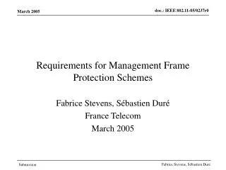
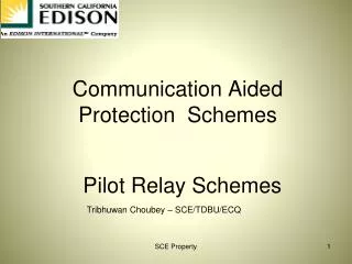
Communication Aided Protection Schemes. Pilot Relay Schemes. Tribhuwan Choubey – SCE/TDBU/ECQ. Introduction. Relays at the Transmission terminals talk with each other using telecommunication media. Pilot relays do not pick up for faults outside their defined zone of protection.

E N D
Communication Aided Protection Schemes Pilot Relay Schemes Tribhuwan Choubey – SCE/TDBU/ECQ SCE Property
Introduction • Relays at the Transmission terminals talk with each other using telecommunication media. • Pilot relays do not pick up for faults outside their defined zone of protection. • Pilot relays pick up instantaneously for faults within their defined zone of protection. • For increased reliability some type of backup protection is also provided SCE Property
2- Zone Distance Relay SCE Property
Pilot relay telecommunication SCE Property
Relay communication • Leased Telephone Line ( 56 or 64kbps over copper) • Power Line Carrier (PLC – 64kbps) – Twisted copper wire for 2/ 3 terminals • Microwave or UHF radio (Multiplexed – 1.544 mbits/ sec DS1 signal – 24 channels) • Dedicated Optical Fiber (Single Mode – 10 miles or Multi mode – 60 miles) • SONET (Multiplexed Symmetrical Optical Network - Synchronous) • T1 Multiplexing – 1.544 mbits/ sec (Asynchronous – voice and data communication) SCE Property
Microwave Tower SCE Property
Microwave Tower SCE Property
Microwave Telecom Equipment • Microwave Radio frequency spectrum: 1850-19909, 2130-2200, 6525-6875 and 12200-12700 MHz • Operation: Two frequency duplex operation • Telecom Equipment: Transmitters, Receivers, Order wires, Filters, Power Supplies, switching devices • Microwave RF Apparatus specifications: T-8505 • Carrier Frequency and Bandwidth : FCC Rules 94.65 and 94.71 • Frequency Stability: FCC rules 94.67 • Baseband I/O level: < -35dBm/ -15dBm per channel • Power Supply: 48V DC SCE Property
Microwave Telecom Equipment • Each terminal is equipped with hot standby transmitter. • Switching circuitry is bilateral in between transmitters • The input to the receivers from the antenna is connected through an RF Hybrid • Switching time for manual operation < 20 msec. • Switching time for automatic operation < 25 msec. • Operation of either or both of these switches cause a “Guard” or “Off Normal” lamps • Hot standby operation of Transmitters and Receivers allows uninterrupted operation on failure of one equipment SCE Property
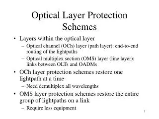
SONETcommunication SONET - Synchronous Optical Network SCE Property
SONET Data Service SCE Property
Fiber optic communication SCE Property
Fiber optic Data Losses SCE Property
T1 Extended Super Frame SCE Property
Categories of Pilot Relaying Following categories of protection schemes are typically applied in pilot relaying. • Phase comparison • Directional comparison blocking • Remote tripping • Transfer trip • Line differential SCE Property
Pilot Relaying Philosophy 500 KV Pilot Relaying Schemes: • Redundant Pilot relaying systems • Redundant Transfer Trip relaying systems • One set of electromechanical relays as backup protection system. • Mix of communication system like Power Line Carrier (PLC) and Microwave are used for communication redundancy SCE Property
Pilot Relaying Philosophy 220 KV Pilot Relaying Schemes: • One Pilot relaying systems • One set of electromechanical relays or another Pilot relaying scheme with microwave as communication channel are used as backup protection system • Mix of communication system like Power Line Carrier (PLC) or Microwave are used for communication redundancy SCE Property
Pilot Relaying Philosophy • Principle of Differential Relaying is applied for instantaneous tripping for in zone faults • Four wires, normally termed as Pilot Wires, run in between substations to compare current between terminals (Typical F/C 15ms – 25ms) • HCB Relays from Westinghouse (ABB) are predominantly used as Pilot relays for lines up to 20 miles. • HCB relay contains Sequence filters, DC polar unit with Operating and Restraining coils, Insulating and Saturating Transformers SCE Property
Differential Relaying Philosophy SCE Property
Pilot Relaying Philosophy SCE Property
Pilot Relaying Philosophy • Westinghouse (ABB) LCB relays are used for Pilot Relaying for Transmission lines from 20 to 250 miles length. • The communication medium is Fiber Optics • The relay contains Sequence Filter, Transmitter Modulator ( 1 Ph -> FM), Receiver De Modulator (FM –> 1Ph), Phase comparison Unit (compare currents at Local/ Remote terminal) • For out of zone fault, the signals would be out of phase and in phase for fault in the zone. SCE Property
Pilot Relaying Philosophy SCE Property
Phase Comparison Relaying • Relay combination used with phase comparison systems are SLD or SKBU carrier relaying and CO( Residual Ground)/ ICC (Directional ground). • Phase comparison relaying compares current phasors at local and remote terminals. Line and Neutral potential are not required. • Faults in the protected zone would cause the currents to trip in less than 3 cycles • Fault detector turns on carrier signal during Fault • Transmitter generates blocking pulse during negative half cycle. • During external fault both transmitters produce additive blocking pulse for the full cycle. • During internal fault out of phase pulse cancel blocking pulse, allowing the relay to trip. SCE Property
Phase Comparison Relaying • SPCU relays are used for Phase comparison for Phase and Phase to Ground faults • Microwave is used for communication of current phasors. Guard signals are transmitted for communication health. Relay trips in 9 cycles on loss of guard signal. Noise on communication channel will block tripping. • SRU/ UIO as auxiliary relay for annunciation purpose • Directional comparison blocking ( SLYP/ SLYN) compares current direction at both terminals to determine in zone or out of zone faults to block tripping • SLYP provides Zone1 element ( 80% of line: instantaneous trip with TT), Zone2 (125% of Line) (Instantaneous for in zone fault and TT or blocking signal for out of zone faults) and Zone3 (180% of line sends blocking signal out of zone faults) • SLYN provides Directional overcurrent, trip for in zone faults and block for out of zone faults SCE Property
DCB Philosophy • Impedance relays trip instantaneously for z1 faults covering 80% of line • Over reaching impedance relays with z2 faults operate with time delay covering 125% of the line • Directional comparison Blocking (DCB) allows over reaching relays to trip instantaneously by blocking out of zone faults • Thus Phase Distance Relays and ground over current relays can provide instantaneous protection for in zone faults • Only one Communication channel is used for sending blocking signal only , used with PLC schemes SCE Property
DCB Relaying Philosophy SCE Property
Typical Transfer Trip Relaying • Transfer Trip schemes are another flavor of Directional comparison schemes, where two relays communicate to trip rather than block. • The two frequencies transmitted through two communication channels are: • Guard frequency to keep guard relays closed to block tripping over channel noise • Tripping Frequency to allow tripping relay to pickup and trip circuit breakers • Basic Transfer trip Schemes: • Direct Transfer Trip (DTP) • Direct Overreaching Transfer Trip (DOTT) – 125% • DirectUnder reaching Transfer Trip (DUTT) – 80% • Permissive Transfer Trip • Permissive Overreaching Transfer Trip (POTT) – 125 % • Permissive Under reaching Transfer Trip (PUTT) –80% SCE Property
Typical PUTT Relaying Scheme • Typical PUTT Relaying Scheme would have following components: • 3 GCX (Directional Distance Relays ( Z1, Z2 and Z3 protection) • Z2 and Z3 timer provides backup delayed tripping to POTT • 1 JBCG directional Ground Relays • 2 Transmitter and Receiver systems • 2 Transfer Trip communication channels • 1 Ground Fault detector relay (SC) • 1 HD Balance relay to be used as backup for Transfer Tripping • Trip signal at Remote terminal is enabled only when both transmitters are keyed to trip simultaneously, if Local and Remote permissive trip signal is available • Loss of Guard signal for six cycles continuously will disable the channel equipment and if it continues for more than 2 seconds resulting into alarm and if alarm is continuous, then the relays are made inactive SCE Property
PUTT Relaying Philosophy SCE Property
Typical POTT Relaying Scheme • Typical POTT Relaying Scheme would have following components: • 3 CEY (Impedance relay with zone 2 timer- starts at fault detection) • 1 SLYG directional Ground Relays • 2 GE Type 40 Transmitter and Receiver systems • 2 Transfer Trip communication channels (Primary/ Secondary) • When a terminal receives the shift from Guard to trip frequency and a trip signal is present from Local relay, the local CB will trip • Zone 2 timer is reset after the fault is cleared • If zone 2 timer times out it will trip the local CBs irrespective of Tone signals from receiver to provide a backup protection • If the fault is out of zone, then relay at the remote terminal will not pickup and removes the Guard frequency, preventing local relay to trip • Loss of Guard signal for six cycles continuously will disable the channel equipment and continuous alarm will deactivate the relays SCE Property
POTT Relaying Philosophy SCE Property
Digital POTT Relaying Scheme • Some of the new microprocessor based relays being used in the industry are as follows: • D60 Hybrid POTT Relays from GE • L90 Differential with DTT from GE • PLC Transfer Trip via RFL-9780 • MW Transfer Trip via RFL-9745 • FO Transfer Trip via RFL-9745 • SEL 421 – POTT/ DTT with PLC from Schweitzer Electric • SEL-311L – Differential with DTT from Schweitzer Electric • SEL-311C – POTT from Schweitzer Electric • Communication Details: • Serial RS485 communication Port • Ethernet full duplex network • Modbus communication Protocol • IEC61850 communication data architecture • Communication speed 9600MB/sec SCE Property
Issues in Relay Communication • Optical fiber cable damage or too high output from communications interface causes loss of channel signal alarm and may need attenuation or proper splice tray connection. • T1 communication standard (DS1) requires transmittal of at least one pulse within any eight bit sequence. Loss of synchronization and unlocked frequency clocks could result in frame slips. Resulting in data loss. • Leased Phone Lines need CSU channels as demarcation point between vendor and customer’s communication terminals. Interference on the cable/ CSU may cause loss of signal. SCE Property
Issues in Relay Communication • High induced voltages across pilot wire possibly caused by faults or lightning could cause induced fluxes and rise in ground voltage. This is remediated through provision of neutralizing reactors, voltage limiting circuits or surge suppressors. • Open or shorted pilot wires are monitored and resulting erroneous trip signals are blocked. SCE Property