Download
1 / 31
350 likes | 600 Views
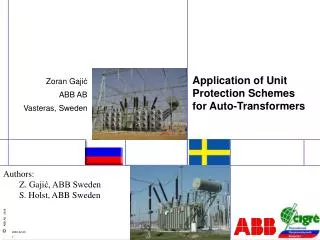
Application of Unit Protection Schemes for Auto-Transformers. Zoran Gaji ć ABB AB Vasteras, Sweden. Authors: Z. Gaji ć, ABB Sweden S. Holst, ABB Sweden. Auto-Transformer. An auto-transformer is a power transformer in which at least two windings have a common part

E N D
Application of Unit Protection Schemes for Auto-Transformers Zoran Gajić ABB AB Vasteras, Sweden • Authors: • Z. Gajić, ABB Sweden • S. Holst, ABB Sweden
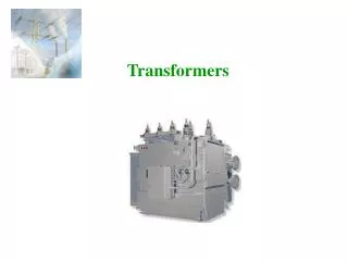
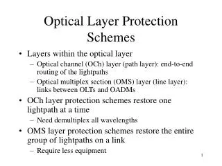
Auto-Transformer • An auto-transformer is a power transformer in which at least two windings have a common part • Typically auto-transformers are used to interconnect two electrical networks with similar voltage levels (e.g. system intertie transformer) • In practice auto-transformer tertiary delta winding is normally included. It serves to limit generation of third harmonic voltages caused by magnetizing currents and to lower the zero sequence impedance for five-limb core constructions or for auto-transformers built from three single phase units
Auto-Transformer has Dual Rating • It can be shown that power is transferred in two different ways through an auto-transformer. • One part of the power is transferred by galvanic connection and the other part is transferred via magnetic circuit (i.e. transformer action) • Auto-transformer is cheaper that corresponding two/three winding power transformer design • Possible problem with short circuit current withstand
One three-phase unit Typically has five-limb core Three single-phase units connected to form three-phase group Auto-transformer Construction
Based on autotransformer ampere-turn balance 87T Based on the first Kirchhoff’s law between galvanically interconnected parts 87B Possible Differential Protection Principles
Restricted Earth-Fault Zero-sequence current based Dedicated delta winding unit protections Special Unit Protections
87T Differential protection using CT1 and CT2 • SBase=Throughput Power(400MVA) • Tertiary delta winding can not be loaded • Mandatory zero sequence current reduction
87T Differential protection using CT1, CT2 and CT3 • SBase=Throughput Power(400MVA) • Tertiary delta winding can be loaded • Mandatory zero sequence current reduction
87T Differential protection using CT1, CT2 and CT7 • SBase=Throughput Power(400MVA) • Tertiary delta winding can be loaded • CT location within delta winding requires “special attention” • Zero sequence current reduction not required if it is a five-limb or single-phase construction
87T Differential protection using CT1, CT2 and CT7 * Influenced by CT location within tertiary delta winding
87T Differential protection using CT1, CT5 and CT7 • SBase=Magnetic Power(169MVA) • Tertiary delta winding can be loaded • CT location at neutral point and within delta winding requires “special attention” • Zero sequence current reduction not required if it is a five-limb or single-phase construction • MV (i.e. 220kV) bushings not protected!
87T Differential protection using CT1, CT5 and CT7 Influenced by CT5 location in neutral point * Influenced by CT7 location within tertiary delta winding
87T Differential protection using CT1, CT2, CT7 and CT8 • SBase=Throughput Power(400MVA) • Tertiary delta winding can be loaded • Double CT location within delta winding requires “special attention” • Relay with four restraint inputs required • Mandatory zero sequence current reduction
87T Differential protection using CT1, CT2, CT7 and CT8 * Influenced by double CT location within tertiary delta winding
87T Differential protection using CT1, CT5, CT7 and CT8 • SBase=Magnetic Power(169MVA) • Tertiary delta winding can be loaded • CT location at neutral point and within delta winding requires “special attention” • Relay with four restraint inputs required • Zero sequence current reduction not required if it is a five-limb or single-phase construction • MV (i.e. 220kV) bushings not protected!
87T Differential protection using CT1, CT5, CT7 and CT8 Influenced by CT5 location in neutral point * Influenced by CT7, CT8 location within tertiary delta winding
87B Differential protection using CT1, CT2 and CT6 • SBase=Throughput Power(400MVA) • Zero sequence current reduction not required • Tertiary delta winding can be loaded • Not sensitive for winding turn to turn faults
REF protection using CT1, CT2 and CT4 • Base quantity is current (either CT2 or W2 rating) • Tertiary delta winding can be loaded but it is not protected • Operates only for phase to ground faults
Dedicated unit scheme for tertiary winding • Use simple I> relay to provide only earth-fault protection for tertiary delta winding
Field Recording CT1 CT5 CT2 CT4 & CT7 • External L2-Gnd fault which before clearing evolved into a L2-L3-Gnd fault • CT1, CT2, CT4 and CT7 currents recorded • CT5 current calculated • Delta winding not loaded, thus CT7 currents are identical in all three phases
Conclusion • The following data are crucial for proper application of the selected differential protection scheme for Auto-transformer: • Which base quantities (i.e. power, no load voltage and current) shall be used • Which vector group shall be entered • Whether or not zero sequence current elimination shall be enabled
Conclusion • Selection of unit protection schemes for particular auto-transformer application depends on: • Available CTs • User preference • Previous experience
СПАСИБО ЗАВНИМАНИЕ! THANK YOU!