Download

1 / 42
420 likes | 520 Views
Explore the key concepts, tradeoffs, and benefits of a Parallel Packet Switch for high-speed networking and Quality of Service support. Detailed discussions on architecture alternatives and ideal scenarios are presented.

E N D
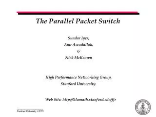
The Parallel Packet Switch Sundar Iyer, Amr Awadallah, & Nick McKeown High Performance Networking Group, Stanford University. Web Site: http://klamath.stanford.edu/fjr
Contents • Motivation • Key Ideas • Speedup, Concentration, Constraints • Mimicking an OQ-Switch • FIFO : A Speedup of 2 suffices • Enabling QoS in a PPS • PIFO: A Speedup of 3 suffices • Multicasting in a PPS • An optimal strategy • Motivation for a Distributed Algorithm • Tradeoffs • Observation & Conclusions
Motivation • To build • a switch with memories running slower than the line rate • an extremely high-speed packet switch • a switch with a highly scaleable architecture • To Support • Quality of Service • To have • Redundancy “I want an ideal switch”
Architecture Alternatives - Refresher Ideal ! Y QoS Support • An Ideal Switch: • The memory runs at lower than line rate speeds • Supports QoS • Is easy to implement PPS Switch ? CIOQ Switch Output Queued Input Queued X 1x Ease of Implementation 2x Nx Z Memory Speeds
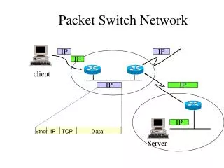
What is a Parallel Packet Switch ? - Refresher A parallel packet-switch (PPS) is comprised of multiple identicallower-speed packet-switches operating independently and in parallel. An incoming stream of packets is spread, packet-by-packet, by a de-multiplexor across the slower packet-switches, then recombined by a multiplexor at the output.
Key Ideas in a Parallel Packet Switch • Key Concept - “Inverse Multiplexing” • Buffering occurs only in the internal switches ! • By choosing a large value of “k”, we would like to arbitrarily • reduce the memory speeds within a switch Can such a switch work “ideally” ? Can it give the advantages of an output queued switch ? What should the multiplexor and de-multiplexor do ? Does not the switch behave well in a trivial manner ?
Definitions - Refresher • Output Queued Switch • A switch in which arriving packets are placed immediately in queues at the output, where they contend with packets destined to the same output waiting their turn to depart. • “We would like to perform as well as an output queued switch” • Mimic (Black Box Model) • Two different switches are said to mimic each other, if under identical inputs, identical packets depart from each switch at the same time • Work Conserving • A system is said to be work-conserving if its outputs never idle unnecessarily. • “If you got something to do, do it now !!”
Ideal Scenario Output-Queued Switch Multiplexor Demultiplexor (R/3) 1 R R (R/3) 1 1 Demultiplexor Multiplexor (R/3) R R Output-Queued Switch 2 2 (R) 2 (R/3) Demultiplexor Multiplexor R R (R/3) 3 3 Output-Queued Switch k =3 Multiplexor Demultiplexor (R/3) R R (R/3 N=4 N=4 Packets destined to output port two
Potential Pitfalls - Concentration “Concentration is when a large number of cells destined to the same output are concentrated on a small fraction of internal layers” Output-Queued Switch Multiplexor Demultiplexor (R/3) 1 R R (R/3) 1 1 Demultiplexor Multiplexor (R/3) R R (2R/3) Output-Queued Switch 2 2 2 (R/3) Demultiplexor Multiplexor R R (R/3) 3 3 Output-Queued Switch k =3 Multiplexor Demultiplexor R R (R/3) N=4 N=4 Packets destined to output port two
Can concentration always be avoided ? R R R C3 C1 A R 1 A 1 C1:A, 1 R B R R R 2 B R R 2 C2:A, 2 C2 R R R C R 3 C 3 C3:A, 1 t=0’ t=0 Cells arriving at Cells departing at (c) (d) R R C3 C3 R 1 A C4:B, 2 1 R B R R R 2 B R R 2 R R C R 3 C5 C4 R C C5:B, 2 3 t=1 Cells arriving at t=1’ Cells departing at
Link Constraints • Input Link Constraint- An external input port is constrained to send a cell to a specific layer at most once every ceil(k/S) time slots. • This constraint is due to the switch architecture • Each arriving cell must adhere to this constraint • Output Link Constraint • A similar constraint exists for an output port Demultiplexor Demultiplexor 2R/k 2R/k R R After t =4 After t =5 A speedup of 2, with 10 links
AIL and AOL Sets • Available Input Link Set: AIL(i,n), is the set of layers to which external input port i can start sending a cell in time slot n. • This is the set of layers that external input i has not started sending any cells to within the last ceil(k/S) time slots. • AIL(i,n) evolves over time • AIL(i,n) is full when there are no cells destined to an input for ceil(k/S) time slots. • Available Output Link Set:AOL(j,n’), is the set of layers that can send a cell to external output j at time slot n’ in the future. • This is the set of layers that have not started to send a new cell to external output j in the last ceil(k/S) time slots before time slot n’ • AOL(j,n’) evolves over • time & cells to output j • AOL(j,n’) is never full as long as there are cells in the system destined to output j.
Bounding AIL and AOL • Lemma1: AIL(j,n) >= k - ceil(k/S) +1 • Lemma2: AOL(j,n’) >= k - ceil(k/S) +1 k ceil(k/S) -1 Demultiplexor k - ceil(k/S) +1 AIL(i,n) At t =n
Thumb Rule • When analyzing a PPS we can follow any of the three identical lines of argument • The intersection of all the available link sets is non empty. • The sum of the sizes of the p available link sets is greater than (p-1)k • The sum of all the given constraint sets is lesser than k
Theorems • Theorem1: (Sufficiency) A PPS can exactly mimic an FCFS- OQ Switch if it guarantees that each arriving cell is allocated to a layer l, such that l € AIL(i,n) and l € AOL(j,n’), (i.e. if it meets both the ILC and the OLC) U AIL(i,n) AOL(j,n’) The intersection set • Theorem2: (Sufficiency) A speedup of 2k/(k+2) is sufficient for a PPS to meet both the input and output link constraints for every cell.
Quality of Service: PIFO - Logical View 8 7 6 5 4 3 7 2 6 5 1 8 4 3 2 1 • Logical View • Highest Priority First • 3 priority levels • 3 logical queues • Each logical queue is FIFO
PIFO Queues - Physical View 4 3 7 2 6 5 1 8 8 8 1 8 5 1 8 6 5 1 8 6 5 2 1 • Physical View • Single Queue • The queue is PIFO • The HOL cell is serviced first 8 7 6 5 2 1 8 7 6 5 3 2 1 8 7 6 5 4 3 2 1 Timeline
PIFO in PPS – Candidates for Insertion R/k 2 R/k 7 2 R/k 11 6 1 R/k 11 6 1 . . 12 4 . . 12 4 10 5 10 5 9 9 7 14 Individual Output Queues 14 7 13 7 13 7 8 3 8 3 7 Present Order
PIFO in PPS – After Insertion R/k 7 2 R/k 2 R/k 11 6 1 R/k 12 6 1 . . 12 4 . . 13 4 10 5 11 5 9 10 7 14 7 15 7 Individual Output Queues 13 7 14 8 8 3 9 3 ILC 7 New Order
Constraints for PIFO • Cell must not be sent to a layer which belongs to • OLC(j,n’) • OLC(j,n’+([k/S]-1)) • Cell must meet the ILC constraints ! • There always exists a layer if • ([k/S] -1) + ([k/S] -1) + ([k/S] -1) < k • Theorem2: (Sufficiency) A speedup of 3k/(k+3) is sufficient for a PPS to mimic a PIFO OQ-Switch.
Multicasting in a PPS • What is it ? • One cell - many outputs • That’s cheating ! • How can we do it ? • Copy multicasting • Fanout multicasting • What is the problem ? • Too many output constraints • Too much speedup required
Demultiplexor R 2 Demultiplexor R 3 Demultiplexor R Copy & Fanout Multicasting ……. 1 Output-Queued Switch Multiplexor Demultiplexor (R/k) (R/k) 1 R R 1 1 Multiplexor R Output-Queued Switch 2 2 Multiplexor R 3 Output-Queued Switch k =3 Multiplexor R N=4 N=4
Demultiplexor R 2 Demultiplexor R 3 Demultiplexor R Copy & Fanout Multicasting ……. 2 Output-Queued Switch Multiplexor Demultiplexor (R/k) (R/k) 1 R R 1 1 Multiplexor R Output-Queued Switch 2 2 Multiplexor R 3 Output-Queued Switch k =3 Multiplexor R N=4 N=4
Demultiplexor R 2 Demultiplexor R 3 Demultiplexor R Copy & Fanout Multicasting …. 3 Output-Queued Switch Multiplexor Demultiplexor (R/k) (R/k) 1 R R 1 1 Multiplexor R Output-Queued Switch 2 2 Multiplexor R 3 Output-Queued Switch k =3 Multiplexor R N=4 N=4
Copy Multicasting • Maximum fanout of an multicast packet is m • FIFO • Each copied cell is unicast • A speedup of m * 2k/(k+2) --->2m suffices • PIFO • A speedup of m * 3k/(k+3) ----> 3m suffices
Fanout Multicasting - FIFO • Maximum fanout of an multicast packet is m • FIFO • Each cell has to meet one ILC constraint • Each cell has to meet “m” OLC constraints • A speedup of m +1 suffices U U AIL(i,n) AOL(j,n1’) AOL(k,n2’) Cell destined to output(j,k). Choose layer 4
Fanout Multicasting - PIFO • PIFO • Each cell has to meet one ILC constraint. • Each cell has to meet “2m” OLC constraints • A speedup of 2m +1 suffices
An Optimized Strategy for Multicast • Assume that • A single cell is ‘copy multicast’ into a maximum of q parts. • Hence each cell must be fanout multicast at least Ceil(m/q) times • Input link constraint • (k/s)q - q • Output link constraint for a specific output • (k/s) -1 • Key : Choose in parallel !, ILC is the same • Speedup Condition • ILC + (m/q) OLC < k • (q + m/q)(k/s -1) < k.
An Optimized Strategy for Multicast .. • The speedup is minimum when • F(q) = (q + m/q) is minimized. • q= sqrt(m) • Hence we get • S is the harmonic mean of 2 sqrt(m) and k • S > [2sqrt(m) * k / 2 sqrt(m) +k] • S -------> 2 sqrt(m), for large k. • Note that this reduces to 2k/k+2 when m =1.
Optimized Multicasting Output-Queued Switch Multiplexor Demultiplexor (R/k) (R/k) 1 R R 1 1 Demultiplexor Multiplexor R R Output-Queued Switch 2 2 2 Demultiplexor Multiplexor R R 3 3 Output-Queued Switch k =3 Multiplexor Demultiplexor R R N=4 N=4
Summary of Results • CPA - Centralized PPS Algorithm • Each input maintains the AIL set. • A central scheduler is broadcast the AIL Sets • CPA calculates the intersection between AIL and one or more AOL’s • CPA timestamps the cells • The cells are output in the order of the global timestamp • If the speedup S >= 2 sqrt(m), then • CPA can perfectly mimic a FCFS multicast OQ switch • If the speedup S >= 3 sqrt(m), then • CPA can perfectly mimic a PIFO multicast OQ switch
Motivation for a Distributed Solution • Centralized Algorithm not practical • N Sequential decisions to be made • Each decision is a set intersection • Does not scale with N, the number of input ports • Ideally, we would like a distributed algorithm where each input makes its decision independently. • Caveats • A totally distributed solution leads to concentration • Tradeoff • Give away work conservance for mimicking within a constant factor
Potential Pitfall “If inputs act independently, the PPS can immediately become non work conserving”
Main Idea - Load Balancing • Conservative Available Output Link Set • Define CAOL • CAOL is a subset of AOL • Min size of AOL = (k-k/s +1) • Min size of AIL = (k-k/s +1) • The smallest size amongst all AOL subsets which will allow at least one layer in the intersection is k - min|AIL| • CAOL consists of the (k/s -1) “oldest” layers used by an output. • CAOL is maintained by each input • In general we can prevent a layer from appearing in the AOL till k -k/s +1 cells have been sent to it to that output. • Result : • For any given output a layer is used only after k -k/s +1 cells to that output are sent .
Comparison with Output Queued Switches Output Queued Switch . . p . . . . . . . . 3 2 1 R Parallel Packet Switch sR/k . . . . . 1 sR/k . . p’ . . 6 2 sR/k . . . . 3 4 sR/k . . . . . . 5
Comparison with Output Queued Switches .. OQ: Set P => Set of all cells queued in front of cell p including p . . p . . . . . . . . 3 2 1 R PPS: Set P’ => Set of all cells queued in front of cell p’ including p’ sR/k . . . . . 1 sR/k . . p’ . . 6 2 sR/k . . . . 3 4 sR/k . . . . . . 5
Crux of Argument OQ; Set P => Set of all cells queued in front of cell p including p . . p . . . . . . . . 3 2 1 R PPS: Set P’ => Set of all cells queued in front of cell p’ including p’ sR/k . . . . . 1 sR/k . . p’ . . 6 2 sR/k . . . . 3 4 sR/k . . . . . . 5
Predicting the Departure of a Cell in a PPS • |P| = Sum |P i| • |P’| <= Sum{Ceil [|P i|/ (k -k/s +1)]} • |P’| <= Ceil{p/(k-k/s +1)} + N • There are not more than Ceil{p/(k-k/s +1)} + N cells before the cell p’ in the PPS. • In a PPS for every k external time slots not more than s cells can leave a layer. • Hence cell p’ leaves at least at { Ceil{p/(k-k/s +1)} + N } (k/s) PPS: Set P’ => Set of all cells queued in front of cell p’ including p’ sR/k . . p’ . . 6 2
Speedup Required OQ; Set P => Set of all cells queued in front of cell p including p . . p . . . . . . . . 3 2 1 p R PPS: Set P’ => Set of all cells queued in front of cell p’ including p’ . . p’ . . 6 2 sR/k Ceil{p/(k-k/s +1)} (k/s) • {Ceil{p/(k-k/s +1)} + N } (k/s) < p • Keep constant delay of Nk/s aside. • Ceil{(p/k-k/s +1)} < p • This gives S >= 2k/k+1
Observations • A re-sequencing buffer will be required. • Any PIFO queue can be modeled as a set of x FIFO queues, where “x” is the number of classes of service. • A speedup of two suffices for an PIFO queue provided we can do with a delay of xNk/s. • A speedup of three suffices for certain PIFO queues with a delay of Nk/s. • Important • The delay is not significant because we are talking of time slots of the order of picoseconds or smaller
Conclusions & Future Work PIFO Timestamps have to be real numbers Implementation on the output • Study PIFO for distributed algorithms • Who decides the PIFO order ??