Download
1 / 57
580 likes | 809 Views
Explore the concepts of magnetism including magnetic fields, materials, and forces. Learn about magnets, magnetic fields, Earth's magnetic field, and the interaction between currents and magnetic fields. Discover the magnetic properties of iron, steel, cobalt, and nickel. Understand the forces exerted by magnetic fields on current-carrying conductors and wires. Practice solving problems and interpreting magnetic field patterns.

E N D
Concept Map - Magnetism • Magnetic materials • Magnets • Domains • Poles • Repulsion • Attraction • Magnetic Fields (strong and weak) • Compass • Earth’s magnetic field
Magnetic Fields • Magnetic materials; iron, steel, cobalt and nickel. • Magnetic force acts from the poles of a magnet. • Like poles repel, Opposite poles attract. • Magnetic field lines – 3D lines which tiny bar magnets lie along. A compass aligns itself with the Earth’s magnetic field (magnetic poles actually reversed!) unless a stronger magnet is present. • Magnetic field lines run from N to S. • Neutral Points – where magnetic fields cancel out. Bar magnets exert equal forces. • Field is strongest in regions of dense field lines. • Field is weakest in regions of sparse field lines.
The density of field lines indicates the strength of the field Weak Field Strong Field
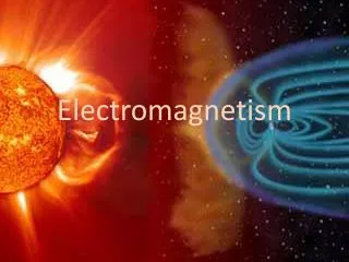
The Earth’s Magnetic Field Earth’s surface Earth’s surface Earth’s surface
Earth’s surface Earth’s surface Earth’s surface The Earth’s Magnetic Field Angle of field line to Earth’s surface changes with latitude – vertical at the poles and horizontal near the equator. In the UK, the field lines are about 70o to the horizontal.
In London the Earth’s magnetic field has a magnetic flux density of 4.8 × 10⁻⁵ T at 66o to the horizontal as shown in the diagram. Calculate the magnitude of the horizontal component of the Earth’s magnetic field in London. Horizontal component = 1.95 x 10⁻⁵ T (2)
The Magnetic Field of a Wire The magnetic field around a current carrying wire is a series of concentric rings. The direction of the field lines can be determined using the right hand corkscrew rule. The strength of the field can be increased by increasing the current. Field Lines Current
Representing Currents • Wire carrying current out of page • Wire carrying current into page
The Magnetic Field of a Coil The overall field around a coil is the sum of the fields around each individual wire.
The Magnetic Field of a Solenoid The magnetic field around a solenoid resembles that of a bar magnet. Inside the solenoid the field lines are parallel to one another. We say it is a uniform field. The field strength can be increased by increasing the current.
Exam Questions 1. Two long parallel wires R and S carry steady currents in the same direction. The diagram is a plan view of this arrangement. The directions of the currents are out of the page. In the region enclosed by the dotted lines, draw the magnetic field pattern due to the current in wire R alone. Show at least three field lines. Show on the diagram the direction of the magnetic field at P.
The diagram shows part of a long straight copper wire through which there is a direct current. Three plotting compasses are positioned as shown: (1) just above the wire, (2) alongside the wire, (3) just below the wire. Deduce the direction of the current in the wire. Complete the diagram by adding the pointer to compass (3). Explain why the pointer in compass (2) settles in the direction shown.
http://schools.matter.org.uk/Content/MagneticFields/Default.htmhttp://schools.matter.org.uk/Content/MagneticFields/Default.htm
The Catapult Effect A wire carrying a current has its own magnetic field. When such a wire is in another field, the two fields interact to produce a force on the wire. We measure the strength of the field in terms of the force exerted on the wire. How do the fields interact to the left and right of the wire? Right – opposite directions so cancel. Left – same direction – reinforce getting distorted. N S
To Do • Force exerted on a current carrying conductor experiment.
Magnetic Field Strength Since the force on a current carrying conductor is proportional to • the current flowing, I, (Amps) • the length of the conductor, l, (metres) • Magnetic field strength/flux density, B, (Tesla) F = BIl sinθ By re-arranging, we can define the strength of the magnetic field, B, as the force per unit length per unit current on a current-carrying conductor perpendicular to the field lines. B = F / Il sinθ Compare with g = force per unit mass
Force Experienced by a Current Carrying Conductor in a Uniform Magnetic Field • The force, F, on the current carrying conductor placed at right angles to the magnetic field is given by: F = BIl • In general, if the angle between the conductor and the magnetic field is θ, then the Force, F, is given by: F = BIlsinθ • The direction of the force is at right angles to both the conductor and the magnetic field (Fleming’s LH Rule). • When the field is parallel to the conductor, θ = 0o, F = 0. • When the field is perpendicular to the conductor, • θ = 90o, F = BIl. F B θ current l
Worked Example 1. Calculate the force exerted on 8 cm of wire when it carries a current of 200 mA at right angles to a field of magnetic flux density 20 mT. F = ? l = 8 cm = 0.08m I = 200 mA = 0.2 A B = 20 mT = 0.02 T F = BIl = 0.02 x 0.2 x 0.08 =0.32 mN
Worked Example 2. A current carrying conductor of length 3.6 cm is placed in a uniform magnetic field of flux density 50 μT. The conductor is at an angle of 25o to the field. Calculate the magnitude and direction of the force on the conductor when the current flowing is 7.2 A. F = BILsinθ = 50 x 10-6 x 7.2 x 3.6 x 10-2 x sin 25o = 5.5 x 10⁻⁶ N = 5.5 μN
3. At a certain point on the Earth’s surface the horizontal component of the Earth’s magnetic field is 1.8 x 10⁻⁵ T. A straight piece of conducting wire 2m long, of mass 1.5g lies on a horizontal bench in an east-west direction. When a very large current flows momentarily in the wire it is just sufficient to cause the wire to lift up of the surface of the bench. State the direction of the current. To the East Calculate the current. l = 2m m = 1.5g = 0.0015 kg, F = 0.0147 N B = 1.8 x 10⁻⁵ T I = F / Bl = 408 A What other noticeable effect will this current produce? Wire melts.
v Q Q l = vt Force on Charge Moving in a Magnetic Field • The moving charge, Q, is the equivalent of an electric current. It travels a length l in time t. • Current = rate of flow of charge = Q / t • By substitution: F = B (Q/t) vt = BQv • When the particle is travelling at an angle θ to the magnetic field, the component of the magnetic flux density at right angles to the direction of travel is Bsin θ. F = BQv sinθ
Worked Example • Calculate the magnitude of the force acting on an electron travelling at 3.0 x 10⁻⁴ ms-1 normal to a magnetic field of flux density 1.7 T. The charge on an electron is -1.6 x 10⁻¹⁹ C. • F = BQv = 1.7 x 1.6 x 10-19 x 3.0 x 10-4 = 8.2 x 10⁻²³ N
θ A B Magnetic Flux, Φ A coil of cross-sectional area A is placed in a uniform magnetic field of magnetic flux density B. The Magnetic flux density is the magnetic flux Φ per unit area. Hence, B = Φ / A So, Φ = BA Where; Φ = Magnetic flux (Weber, Wb) B = Magnetic field strength normal to the area 1 weber = 1 Tesla metre squared (T m2) If the plane of coil is at an angle θ to the magnetic field, then the vector component of the magnetic field through the coil is B sinθ. Therefore: Φ = BA sin θ A B
Worked Example • In an area of 2 m2 there are 6 field lines each representing a flux of 1 Wb. What is the flux density? B = Φ / A = (6 x 1) / 2 = 3 T • A magnetic field has a magnitude of 0.0078 T and is uniform over a circular surface that has radius of 0.10 m. The field is orientated at an angle of of θ = 25o with respect to the surface. What is the flux through the surface? Φ = BA sin θ = 0.0078 x (π x 0.12) sin 25 = 1 x 10⁻⁴ Wb
Worked Example The diagram below shows a car travelling due North in the Earth’s magnetic field. Calculate the magnetic flux through the cross-section of the car when travelling between: a) A and B θ = 60o and A = 4.8 x 1.9 = 9.12 m2 Φ = BA sin θ = 2 x 10-4 x 9.12 x sin 60 = 1.6 x 10⁻³ Wb b) B and C θ = 90o Φ = BA sin θ = 2 x 10-4 x 9.12 x sin 90 = 1.8 x 10⁻³ Wb
Magnetic Flux Linkage, NΦ If the coil has N turns, then the total magnetic flux linkage, N Φ, is; NΦ = BAN sin θ
Worked Example In a coil of 3 m2 and 4 turns there are 12 field lines each representing a flux of 2 Wb. What is the flux density? B = Φ / AN = (12 X 2) / (3 X 4) = 2 T
Electromagnetic Induction We have already seen that when a current carrying conductor (wire) is in a magnetic field it experiences a force. • What happens when the wire is moved relative to the magnet? • What happens when the magnet is moved relative to the wire? • What happens when both the magnet and wire are stationary relative to one another? • What happens when you reverse the direction of movement of the wire or the magnet? • What happens to the magnitude of current as you increase the number of coils, the strength of the magnet and the speed of movement?
Electromagnetic Induction Simple investigations show that: • A current flows when the wire is moved relative to the magnet (use Fleming’s L.H. Rule for direction) • A current flows when the magnet is moved relative to the wire. • No current flows when the magnet and wire are stationary relative to one another. • Reversing the direction of movement of the wire or the magnet reverses the direction of the current. • The magnitude of the current increases as you increase the number of coils of wire, the strength of the magnet and the speed of movement. An emf is induced in a wire/coil in a magnetic field whenever the flux Φ through the wire/coil changes.
Electromagnetic Induction • There is an induced emf whenever: • A conductor ‘cuts’ magnetic field lines • There is a relative motion between a magnetic field and a conductor • There is a change in the strength of the magnetic field ‘linking’ a coil or circuit • A coil is rotated in a magnetic field
It is also possible to induce an EMF in a wire without physical movement. What happens when a current is allowed to flow through circuit A?
Faraday’s Law Faraday’s law states that the magnitude of the induced emf in a circuit is proportional to the rate of change of magnetic flux linkage in the conductor (the rate of cutting of magnetic flux). Induced emf, ε = N dΦ / dt N = Number of turns in coil dΦ / dt = Change in the flux linkage per second. Magnetic Flux Φ Time, t
Changing Magnetic Flux Linkage • If a magnet is dropped through a coil an EMF is induced across the coil as the magnetic flux through it changes. • The poles induced on the coil are such that they oppose the entry and the exit of the magnet (the polarity flips when the magnet is half way through the coil). • The magnet is accelerating under gravity, so leaves the coil slightly faster than it enters. • The induced EMF is therefore greater as the magnet exits, although the EMF is induced for a shorter time.
1 2 Changing Magnetic Flux Linkage As the magnet is dropped from a greater height (1-3), the EMF induced would be greater (dΦ/dt is greater), but would last for a shorter time. 3
N Lenz’s Law and Conservation of Energy Wire pulled down 2. Wire experiences an upwards force. F I 1. Electrons pushed to the left. I S F 1. Apply Fleming’s Left Hand Rule to electrons 2. Apply Fleming’s Left Hand Rule again
Lenz’s Law and Conservation of Energy • The Principle of Conservation of Energy tells us that the induced current flows in a direction such that the associated magnetic field tries to stop the wire moving. • Imagine if it were otherwise; • Move wire through magnetic field. • Magnetic force attracts wire. • Wire moves more. • Using a small amount of energy to move the wire produces more energy. • The Principle of Conservation of Energy is broken, so this must be wrong.
Activity: Which Pole is Induced? • Thrust the north pole of the magnet into the coil, which way does the meter deflect? Which pole is induced?
N S N S S N Lenz’s Law N S S N
Lenz’s Law and Conservation of Energy • The Principle of Conservation of Energy tells us that the induced current flows in a direction such that the associated magnetic field tries to stop the magnet moving. • Imagine if it were otherwise; • Move bar magnet towards coil. • Coil attracts bar magnet. • Bar magnet moves more. • Using a small amount of energy to move the magnet produces more energy. • The Principle of Conservation of Energy is broken, so this must be wrong.
Lenz’s Law Lenz’s law states that the direction of the induced emf is such as to cause effects to oppose the change producing it. Induced EMF, ε = - N (dΦ / dt) dΦ / dt = Change of flux linkage per second. N = Number of turns in coil. The negative sign indicates that the current opposes the change causing it.