Download

1 / 11
110 likes | 238 Views
This document outlines the proposed readout system for the New Small Wheel (NSW) using the RCE/COB architecture. Key requirements include data de-serialization, error correction, and formatting of MM and sTGC data for TDAQ output. The system must support high data volumes, with configurations for VMM2 and GBT. The COB setup offers versatility with network interconnect options, enabling scalability and adaptability to changing protocols. Additionally, we detail the differences between pre-production and production designs, emphasizing system flexibility and performance optimization.

E N D
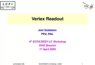
nSW Readout Tony Liss, Ric Claus Rainer Bartoldus, NicolettaGarelli, Mike Huffer, Martin Kocian, Todd Moore, Su Dong, Charlie Young
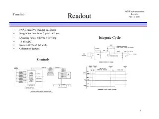
Basic Requirements • Upon receipt of a L1A, the MM and sTGC data must be de-serialized, error-corrected, and formatted. (Feature extraction?) • Formatted MM and sTGC data must be output via S-link to TDAQ. • DCS & Monitoring/Calibration data must be received and distributed. • TTC signals must be received, processed, and distributed. • The VMM2 must be configured and controlled. • The nSW readout must be forward compatible with Phase 2.
Data Volume VMM2: 32 bits/hit MM: 1% occupancy ~2 hits/VMM/L1A, sTGC: 2% (?) occupancy ~4 hits/VMM/L1A L1A @ 200 KHz 13 Mb/s per MM VMM2 , 26 Mb/s per sTGC VMM2 • Channel counting: • MM: 2,097,152 channels32,768 VMM2 • sTGC: 1M channels (?) 16,384 VMM2 • Total data volume: 800 Gb/s for MM+sTGC This assumes 32 bit word for sTGC. Is that true?
GBT Link • 4.8 Gb/s with 3.2 Gb/s user data • From Ken J: 128 VMM2/GBT 256 GBT • MM: 13 Mb/s x 128 = ~1.6 Gb/s • sTGC: 26 Mb/s x 128 saturates the GBT • Assuming same bandwidth out as MM, then half as many VMM/GBT 256 GBT for sTGC too.
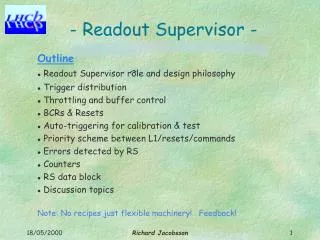
COB • Cluster-On-Board: An ATCA Front Board • A network cluster interconnect • On-board 64 port 10 GE network switch • Configurability allows 1 GE, 10 GE per port or 40 GE XAUI • Extends over the full-mesh backplane to other COBs • 8 SFP+ transceivers provided on the front panel • A carrier of 8 general purpose RCEs • One additional RCE for board management • Potential expansion for DCS duties • A timing distribution system • Can source as well as receive TTC information • Distributed over the dual-star backplane • A BUSY signal aggregator • Distributed over the dual-star backplane
Preproduction COB • Differences between pre and production COB • Move SFP+ from RTM to Front-Board • Move IPMC onto DTM • Break up FTM into two different boards • Move resulting base-board next to P2
Design 1: RCE configured for 5 inputs, 1 output. . . . . . RCEOUT 4 RCEOUT 3 RCEOUT 2 RCEOUT 1 GBT 1-5 GBT 16-20 GBT 11-15 GBT 6-10 RCEout 52 GBT 251-256 RCEIN 2 RCEIN 3 RCEIN 4 RCEIN 1 RCEIN 52 . . . . . . . . . . . . . Ethernet Interconnect . . . . . S-link to ROS
Design 2: RCE configured for 3 inputs, 3 outputs GBT ROL 4.8 Gbps 4 Gbps GBT RCE ROL GBT ROL X 8 for each COB
Design 1 vs. Design 2 • 5 GBTs/(2 RCE) 8 RCE per COB 256+128 GBTs 14 + 8 COBs • 1 ATCA crate each for MM+sTGC • Flexible: Easy to accommodate changing design metrics • Higher speed ROLs • Static or dynamic mapping of inbound to outbound links • On-board data processing available. • Existence proof from CSC • 3 GBTs/RCE 8 RCE per COB 256+128 GBTs 11 + 6 COBs • 1 ATCA crate each for MM+sTGC • Fixed relation between inbound and outbound links • Simple design
Alternate proposed architecture System-specific protocol. Aggregator must deal with all. What if not GBT? This green box is the COB Need system-specific error correction here For dynamic routing, aggregator needs to tell switch how to route data.
Summary • We propose using the RCE/COB as the basic readout element for the nSW • The hardware already exists, satisfies the known requirements, and is already planned for the CSC in 2014. • The system is very flexible and scalable allowing a choice of many different architectures. It can easily adapt to changes in input/output protocols.