Download
1 / 11
110 likes | 233 Views
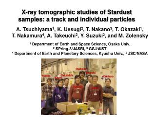
X-ray tomographic studies of Stardust samples: a track and individual particles. A. Tsuchiyama 1 , K. Uesugi 2 , T. Nakano 3 , T. Okazaki 1 , T. Nakamura 4 , A. Takeuchi 2 , Y. Suzuki 2 , and M. Zolensky 1 Department of Earth and Space Science, Osaka Univ. 2 SPring-8/JASRI, 3 GSJ/AIST

E N D
X-ray tomographic studies of Stardust samples: a track and individual particles A. Tsuchiyama1, K. Uesugi2, T. Nakano3, T. Okazaki1, T. Nakamura4, A. Takeuchi2, Y. Suzuki2, and M. Zolensky 1 Department of Earth and Space Science, Osaka Univ. 2 SPring-8/JASRI, 3 GSJ/AIST 4 Department of Earth and Planetary Sciences, Kyushu Univ., 5 JSC/NASA
Two types of tomographic studiesat BL47XU/SPring-8 • 3-D structures of impact tracks • SUBTEAM: Bulk-composition • Projection tomography (high resolution) • Resolution: 0.5 or 0.195 mm/pixel • Samples: 4 tracks* in keystones • with XRF (T. Nakamura) • 2. 3-D structures of individual particles • SUBTEAM: Mineralogy-Petrology • Imaging tomography (ultra-high resolution) • Resolution: 0.0425 mm/pixel • Samples: 4 particles removed from 2 tracks* • with XRD at BL17/PF (T. Nakamura) • * Different tacks
3D structures of impact tracks Projection tomography (0.5 or 0.195 mm/pixel) Samples: 4 tracks (C2126,2,68,0; 32,0; 67,0; 47,0) Photon energy: 10 keV No. of projection: 1500 3-D image: 2000x2000 matrix, 1312 slices XRF Photon energy 15 keV Beam size: 40x40 to 400x260 mm
Procedure • Optical microscopy • Radiography • Whole 2-D image of keystone • (3) XRF • Coarse mode: cover whole track • Fine mode: individual particles • (4) Tomography • Coarse mode: cover whole track • Fine mode: details of a track Optical microscopy Tomography (vertical slice: 5 tiles) XRF Tomography (CT slice) Radiography (7.090 keV: tile image) Sample: C2126,2,68,0
4a/0564 condensed aerogel radial crack particle particle 4b/1008 subtrack-1 subtrack-5 (terminal particle) subtrack-3 main track condensed aerogel CT slice images (C2126,2,68,0) Dark space: track hole with radial cracks Bright wall: condensed aerogel (melted?) with very fine particles? White: captured particles Track is bifurcated into main and sub-tracks. Particles are present along tracks and radial cracks as well as the main track terminal.
radial crack bifurcation subtrack-1 main track main track main track main track slice 219 slice 229 slice 239 terminal particle CT images parallel to the track (C2126,2,68,0) C2126,2,68,0CT images nearly parallel to the track Many particles are present along the main and subtrack-1.
Track: Bird’s eye view (C2126,2,68,0) Gray: track hole and radial cracks Blue: condensed aerogel Red: captured particles Track is bifurcated into 5 or 6. Main and subtracks have terminal particles, respectively. Many particles are present along the bifurcated tracks.
Track size vs. XRF data (C2126,2,68,0) Whole Fe mass: 6.66x10⁻¹¹ g XRF data Estimated mass (whole grain): 7.6x10⁻¹⁰ g Fe mass/track volume: 8.56x10⁻⁶ g/cm3 Estimated whole mass/track volume: 9.7x10⁻⁵ g/cm3 if density=1 g/cm3 : 0.01 vol.% If track volume is proportional to mass, we may evaluate volatile/solid ratio among different tracks. track volume ↔ kinetic E = 1/2mv2 (v∼const.)
d c b a e f Track bulb: Bird’s eye view (C2126,2,68,0) U-shaped radial crack (main: arrow-aandsub: arrow-b) Crack along the central axis of the U-shaped crack: arrow-c Subtrack-4 grows from the central crack: arrow-d (each subtrack seem to grow from a crack) Wavy radial crack: arrow-e Some particles are in radial cracks: arrow-f
3D structures of individual particles Imaging tomography (0.0425 mm/pixel) Samples: 4 particles (C2004.1.44.3, C2054.0.35.6; .5,; .4) Photon energy: 8 keV No. of projection: 3600 3-D image: 2000x2000 matrix, 1312 slices XRD BL17/Photon Factory, Japan The results are presented by T.Nakamura
Conclusions • Whole dust particle • less fragile particles + fragile aggregate of fine particles • ← 3-D structure of track • ← 3-D structures of individual particles • less fragile particles: crystalline • fragile aggregate: amorphous-rich (mixture with aerogel) • Not easy to reconstruct whole dust particle texture completely • by tomography alone • Fe mass/track volume • → whole dust particle/track volueme: ~ 0.01 vol.% • → may estimate volatile/solid ratios of whole dusts particles • among tracks • Crystalline particles • evidence of melting? (SEM/EBSD or TEM study required) • fractured surface