Download
1 / 15
150 likes | 214 Views
Learn about simple computer architecture, I/O programming, memory layout, interrupt vectors, and traps in this course overview. Understand memory-mapped and non-memory-mapped I/O and the interrupt physical model. Gain insights into interrupt sequence and service routines.

E N D
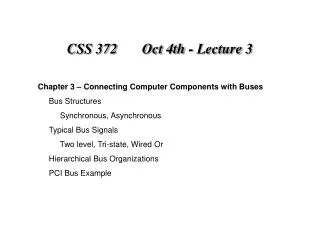
CSS 372 Lecture 1 Course Overview: CSS 372 Web page Syllabus Lab Ettiquette Lab Report Format Review of CSS 371: Simple Computer Architecture Traps Interrupts
Simple Input / Output Memory Mapped I/O – A section of the memory address space is reserved for I/O Registers rather than general memory locations. Think of it as “pseudo” memory. The same instructions are used for general programming and I/O programming. Non-Memory Mapped I/O – There is a separate address space for I/O programming, and an entirely separate set of I/O Instructions.
Simple Memory Mapped I/O Simple Memory Layout: x0000 – x00FF Trap vectors (Supports Software Interrupts) x0020 [x0400] GETC (Read Char from Keyboard) x0021 [x0430] OUT (Write Character to Console) x0022 [x0450] PUTS (Write string to Console) x0023 [x04A0] IN (Prompt, input character from Keyboard, echo character to Console) x0024 [x04E0] PUTSP (Write “packed” string to Console) x0025 [xFD70] HALT (Turn off run latch in MCR) x0100 – x01FF Interrupt Vectors (Supports Hardware Interrupts) x0200 – x2FFF System Programs & Data (“Operating System”) x3000 – xFDFF User Programs Area xFE00 – xFFFF I/O Programming “Registers” (Mapped I/O Registers) xFE00 KBSR [15 {Ready}, 14 {Intr enable}] (Keyboard Status Register) xFE02 KBDR [7:0{ascii data}] (Keyboard Data Register) xFE04 DSR [15{Done}, 14{Intr enable}] (Display Status Register) xFE06 DDR [7:0{ascii data}] (Display Data Register xFFFE MCR [15{Run latch}] (Machine Control Register)
Simple Traps • Execute TRAP “vector” - Operating System Service Routines 2) Trap Vectors are at memory locations [0000:00FF] • Trap Vectors contain addresses of Trap Service Routines • (PC) is loaded into R7 • Address of Trap Service Routine loaded into PC • Service Routine Program executed • Trap service routine program ends with an RET ( (R7) loaded into PC)
Simple Memory Mapped I/O Simple Memory Layout: x0000 – x00FF Trap vectors (Supports Software Interrupts) x0020 [x0400] GETC (Read Char from Keyboard) x0021 [x0430] OUT (Write Character to Console) x0022 [x0450] PUTS (Write string to Console) x0023 [x04A0] IN (Prompt, input character from Keyboard, echo character to Console) x0024 [x04E0] PUTSP (Write “packed” string to Console) x0025 [xFD70] HALT (Turn off run latch in MCR) x0100 – x01FF Interrupt Vectors (Supports Hardware Interrupts) x0200 – x2FFF System Programs & Data (“Operating System”) x3000 – xFDFF User Programs Area xFE00 – xFFFF I/O Programming “Registers” (Mapped I/O Registers) xFE00 KBSR [15 {Ready}, 14 {Intr enable}] (Keyboard Status Register) xFE02 KBDR [7:0{ascii data}] (Keyboard Data Register) xFE04 DSR [15{Done}, 14{Intr enable}] (Display Status Register) xFE06 DDR [7:0{ascii data}] (Display Data Register xFFFE MCR [15{Run latch}] (Machine Control Register)
Interrupt Physical Model • CPU • Memory • Device
Interrupt Physical Model • CPU • General Purpose Registers • PC Storage – R7 • Stack Pointer R6 • Program Status Word (PSW) – Includes • State • Program Priority • Condition Codes (CC) • User stack Pointer Storage – USP.saved • Supervisor Stack Pointer Storage – SSP.saved • Hardware to communicate over the BUS • Memory • User program • Interrupt Service Routine • Operating System • Interrupt Vector Table • Includes an entry that points to the Interrupt Service Routine (Interrupt vector #) • Device • Status/Control Register(s) – Includes: • Interrupt Enable bit • Interrupt bit (sometimes called ready or done) • Priority Level for Interrupt Service Routine (In hardware or firmware) • Interrupt vector number (In hardware or firmware) • Hardware to communicate with CPU over the BUS
Interrupt Sequence • What does the programmer do? • What does the computer do?
Interrupt Sequence • Programmer Action: Enable Interrupts by setting “intr enable” bit in Device Status Reg • Enabling Mechanism for device: When device wants service, and its enable bit is set (The I/O device has the right to request service), and its priority is higher than the priority of the presently running program, and execution of an instruction is complete, then The processor initiates the interrupt • Process to service the interrupt: The Processor saves the “state” of the program (has to be able to return) The Processor goes into Privileged Mode (PSR bit 15 cleared) Priority level is set (established by the interrupting device) The (USP), (R6) USP.saved register (UserStackPointer.saved) The (SSP.saved) R6 (SupervisorStackPointer) The (PC) and the (PSR) are PUSHED onto the Supervisor Stack The contents of the other registers are not saved. Why? The CC’s are cleared • The Processor Loads the PC from the Interrupt vector (vectors in 0100:01FF) • Interrupt Service Routine is executed Ends with an RTI • The stored user PSR (POP into PSR), PC (POP into PC), (R6)SSP.saved, (USP.savedR6), and the next instruction fetched
Allocating Space for Variables 0x0000 • Global data section • All global variables stored here(actually all static variables) • R4 points to beginning • Run-time stack • Used for local variables • R6 points to top of stack • R5 points to top “frame” on stack • New frame for each block(goes away when block exited) instructions PC R4 global data R6 run-time stack R5 0xFFFF
Simple Register Convention R0 : Trap routine pass values R1 – R3 : General purpose R4 : Global variable stack pointer R5 : Frame pointer (or Activation Record pointer) R6 : Stack pointer R7 : Return PC value
Simple Activation Record Format X0000 R6 Function stacked stuff …….. …….. Local Variables Caller’s Frame Pointer (R5) Caller’s Return PC (R7) Function Return Value Function Pass Value n …….. Function Pass Value 1 R5 XFFFF
Simple Function Call Implementation • Caller pushes arguments (last to first). • Caller invokes subroutine (JSR). • Callee allocates space for return value, pushes R7 and R5. • Callee allocates space for local variables. • Callee executes function code. • Callee stores result into return value slot. • Callee pops local vars, pops R5, pops R7. • Callee returns (RET or JMP R7). • Caller loads return value and pops arguments. • Caller resumes computation…