Download
1 / 48
500 likes | 815 Views
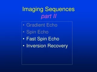
Imaging Sequences part I. Gradient Echo Spin Echo Fast Spin Echo Inversion Recovery. Goals of Imaging Sequences. generate an RF signal perpendicular to 0 generate tissue contrast minimize artifacts. z. 0. y. x. Measuring the MR Signal. RF signal from precessing protons.

E N D
Imaging Sequencespart I • Gradient Echo • Spin Echo • Fast Spin Echo • Inversion Recovery
Goals of Imaging Sequences • generate an RF signal perpendicular to 0 • generate tissue contrast • minimize artifacts
z 0 y x Measuring the MR Signal RF signal from precessing protons RF antenna
Gradient Echo • simplest sequence • alpha flip gradient-recalled echo • 3 parameters • TR • TE • flip angle • reduced SAR • artifact prone
Gradient Echo dephase gradient rephase signal RF pulse FID gradient recalled echo
z z 0 RF y x y x Partial Flip 0 ML M MXY t=t0 t=t0+ MXY =M sin() ML=M cos()
y y x x z z Dephasing in the xy-planeview from the top Mxy dephase Mxy phase coherency phase dispersion
y y Mxy x x z Mxy z phase coherency minus t2* decay phase dispersion Rephasing in the xy-planeview from the top rephase
z 0 y x MR Signal During Rephasing RF signal “echo” RF antenna
T2* decay • occurs between the dephasing and the rephasing gradients • rephasing incompletely recovers the signal • signal loss is greater with longer TEs • decay generates image contrast
T2* decay • T2* decay is always faster than T2 decay • gradient echo imaging cannot recover signal losses from • magnetic field inhomogeneity • magnetic susceptibility • water-fat incoherence
T2 and T2* Relaxation • T2 is the spin-spin relaxation time • T2M is the contribution to relaxation induced by inhomogeneities of the main magnet (predominant factor) • T2MS is the contribution to relaxation induced by magnetic susceptibility in the object
T2 and T2* Relaxation • T2* relaxation influences contrast in gradient echo imaging • T2 relaxation influences contrast in spin echo imaging
Gradient Echopulse timing RF slice phase readout echo signal TE
Gradient Echoadvantages • faster imaging • can use shorter TR and shorter TEs than SE • low flip angle deposits less energy • more slices per TR than SE • decreases SAR • compatible with 3D acquisitions
Gradient Echodisadvantages • difficult to generate good T2 weighting • magnetic field inhomogeneities cause signal loss • worse with increasing TE times • susceptibility effects • dephasing of water and fat protons
Gradient Echochanging TE TE 9 FA 30 TE 30 FA 30 susceptibility effect T2* weighting
Gradient Echomagnetic susceptibility post-surgical change “blooming” artifact
Gradient Echoin-phase / opposed-phase TE 13.42 TE 15.66 in-phase opposed-phase
Water/Fat Dephasing • MR signal is a composite of fat and water in the imaging voxel • water and fat resonate at slightly different frequencies • cyclic variation in relative phase of fat and water resonance results in signal variations dependent on TE times
Gradient Echo • image contrast depends on sequence • conventional GR scan • aka GRASS, FAST • decreased FA causes less T1 weighting • increased TE causes more T2* weighting
Gradient Echo • Spoiled GR • aka SPGR, RF-FAST • spoiling destroys accumulated transverse coherence • maximizes T1 contrast
Gradient Echo • Contrast enhanced GR • aka SSFP, CE-FAST • infrequently used because of poor S/N • generates heavily T2* weighted images
Gradient Echo • other varieties • MTC • T2 - like weighting • IR prepped • 180 preparatory pulse • DE (driven equilibrium) prepped • 90-180-90 preparatory pulses • T2 contrast
Spin Echo • widely used sequence • 90-180-echo • 2 parameters • TR • TE • generates T1, PD, and T2 weighted images • minimizes artifacts
Spin Echo gradient frequency encode readout RF pulse RF pulse signal FID spin echo
z z 0 RF y x y x 900 Flip 0 Before ML=M MXY=0 After ML=0 MXY=M t=t0 t=t0+
y y x x z z Dephasing in the xy-planeview from the top Dephasing begins immediately after the 900RF pulse. Mxy Mxy phase coherency phase dispersion 900 RF t=0 t=TE/2
y y Mxy x x z z Mxy phase coherency minus t2 decay phase dispersion t=TE/2 t=TE Rephasing in the xy-planeview from the top 1800 RF
z z z z y x y x y x y x 1800 Flip dephased rephased 1800 RF 900 RF t=0 t=TE/2 t=TE
Spin Echopulse timing RF slice phase readout echo signal TE
WNMR Race 900 RF t=0
WNMR Race 1800 RF t=TE/2
WNMR Race t=TE
Effects of the 1800 Pulse • eliminates signal loss due to field inhomogeneities • eliminates signal loss due to susceptibility effects • eliminates signal loss due to water/fat dephasing • all signal decay is caused by T2 relaxation only
Spin Echoadvantages • high signal to noise • least artifact prone sequence • contrast mechanisms easier to understand
Spin Echodisadvantages • higher SAR than gradient echo because of 900 and 1800 RF pulses • long TR times are incompatible with 3D acquisitions
Spin Echo Contrast • T1 weighted • short TR (450-850) • short TE (10-30) • T2 weighted • long TR (2000 +) • long TE (> 60) • PD weighted • long TR, short TE
Spin Echo Contrast • T1 weighted - T1 relaxation predominates • Short TE minimizes differences in T2 relaxation • Short TR maximizes differences in T1 relaxation • T2 weighted - T2 relaxation predominates • Long TE maximizes differences in T2 relaxation • Long TR minimizes differences in T1 relaxation
Spin Echo Contrast T1 weighted T2 weighted
Spin Echo Contrast PD weighted T2 weighted
Summary • Detection of the MR signal only occurs in the transverse plane • Gradient echo • Alpha degree pulse, dephase-rephase-echo • Contrast (T1/T2/T2*) depends on sequence type • Spin echo • 90 degree pulse, dephase, 180 degree pulse, rephase-echo • T1 weighted: short TR, short TE • PD weighted: long TR, short TE • T2 weighted: long TR, long TE