Download
1 / 13
130 likes | 272 Views
Elasto-Plastic-Creep Modeling for the First Wall with W Armor. X.R. Wang 1 , S. Malang 2 , M. S. Tillack 1 1 University of California, San Diego, CA 2 Fusion Nuclear Technology Consulting, Germany ARIES-Pathways Project Meeting Bethesda, Washington DC April 4-5, 2011. Outline.

E N D
Elasto-Plastic-Creep Modeling for the First Wall with W Armor X.R. Wang1, S. Malang2, M. S. Tillack1 1University of California, San Diego, CA 2Fusion Nuclear Technology Consulting, Germany ARIES-Pathways Project Meeting Bethesda, Washington DC April 4-5, 2011
Outline • A simple thermal creep model for comparing the ANSYS results to experimental creep data • Structural criteria in time-dependent elasto-plastic-creep analysis • Creep rupture data and Norton Law parameter for Euorfer 97 steel • Elastic-plastic-creep modeling of the first wall with W armor
Thermal Creep Test for ODS EUORFER 97 Steel* • Norton Creep Law : • dεcr/dt=C1σC2e-C3/T • C1,C2, C3 are temperature-dependent creep constants, σ is applied stress, T is temperature • C3=0 • Creep exponent C2: 4.9-5.5 • Assuming C2=5.1, the creep constant C1=3.245E-49 • Applied constant stress:160-200MPa • Applied temperature: 650 °C • Corresponding creep strain rate associated with the steady stage: ~2.25E-7 1/s at applied stress of 160 MPa • Creep strain in primary stage: 1.1% • Creep strain in secondary stage: 1.8% *G. Yu at al, Fusion Engineering and Design, 75-79, 1071(2002)
Comparison of ANSYS Creep results To Creep Tested Data Stress Model (1/4 Specimen) Stress after 80000 s Creep strain after 80000 s Axisymme-tric element behavior Symmetry BC ANSYS modeling, εcr=~1.788% Hand calculation, εcr=~1.8% Exp. Data (Creep-time curve), εcr=~1.8% Deformed shape was exaggerated by a factor of 10
Thermal Creep Modeling of the FW Armor • Temperature of the W-pins is ~ 680 ºC, therefore, thermal creep is not important as a deformation mechanism. W thermal creep begins to become significant around 1500 ºC and above. • As there is not enough creep coefficients for ODS steel (12YWT), and the thermal creep of the ODS steel is not included. (Yu’s creep data only at T=650 ᵒC and σ=160 MPa) • Only F82H material will be considered in the creep model, and the creep data of Eourfer 97 steel will be used in analysis. • Norton model is used in ANSYS, and primary stage is not • included. • Irradiation induced creep is not considered at present • because of difficulty to find the irradiation induced creep data • (Arnold Lumsdaine is helping us to collect the creep data.) *R.L. Klueh et al./J. of Nuclear Materials 307-311 (2002) 455-465.
Structural Criteria in Time-Dependent Elasto-Plastic-Creep Analysis • Structural strain limits: At elevated temperatures where creep occurs, it is generally impossible to avoid strain accumulation. However, it is necessary to limit strain accumulation to avoid excessive structural distortion and fracture. • The calculated maximum accumulated positive principal inelastic (plastic plus creep) strain at the end of life must meet the three limits: • Membrane (strain averaged through the thickness) ≤ 1% • Local (maximum strain anywhere) ≤ 5% • Membrane + bending ≤ 2% • The criteria were used in the design of metallic HTR-components with high application temperature of 750 ᵒC ~1000 ᵒC (INCONEL 617) • Need experts’ opinion on this structural criteria • Need to study ITER SDC-IC (Structural Design Criteria In-vessel Components) and make a comparison *Alfred Snow, “US Elevated Temperature Structural Design Standards: Current Status and Future Direction,” Westinghouse Electric Corporation, 1976.
Creep Rupture Curves of Eurofer Steel(FZK, CIEMAT data)* Creep Rupture Stress, Sr *F. Tavassoli, DEMO Interim Structural Design Criteria, Appendix: A Material Design Limit Data, CEA/DEN/SAC/DMN, Dec. 2002. *M. Rieth, et. al, “EOUOFER 97 Tensile, Charpy, Creep and Structural Tests” FZKA 6911, Oct. 2003.
Creep Coefficients of EUOFER Steel(FZK, CIEMAT data)* • Only the secondary stage is considered. • The creep is ignored at temperature less than 425 ᵒC. • Norton creep equation is expressed by: • dεcr /dt=C1σC2e-C3/T • (creep rate in 10-6/h, σ in MPa in fig.) Allowable creep rate (1/h) corresponding to 1% creep limit (Structural Criteria #1) Norton law parameters for Eurofer Steel • Only C1, C2 and C3 are inputted into ANSYS.
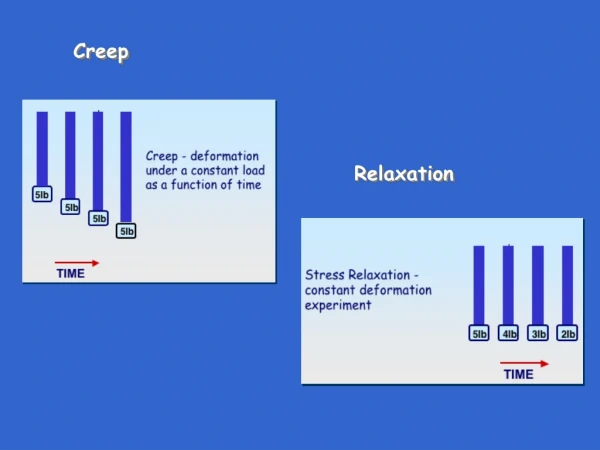
Thermal Loads for the Elasto-Plastic-Thermal Creep Model • Nonlinear structural behaviors of the FW are simulated by a combined elastic, plastic and creep models. • Processes of the fabrication, heat treatment, reactor start-up and normal operation are included in plastic model. • There are no stress, no plastic strain and creep strain during the FW brazing process. • The FW is in the plastic range during braze cool-down. • At this moment, the creep strains are ignored during the heat treatment because of such a short time. 1050ᵒC Elasto-Plastic and Creep Elasto-Plastic 700ᵒC q=1MW/m2 385ᵒC P=10 MPa 20ᵒC Temperature contour during operation
Local Creep Strain of the F82H Node B 525 ᵒC Node A Node A 450 ᵒC Node C 500 ᵒC Node D 500 ᵒC Node B Node C Creep strain at node A Node D Node A Fabrication • The maximum local creep strain of the F82H plate at 1000 hours is ~ 0.17% at the Node A where the local stress occurs caused by sharp corner at the temperature of 450 ᵒC. • Ɛcr=~0.07% at the Node B with maximum temperature of 525 ᵒC. • Ɛcr=~0.05% at the Node C with temperature of 500 ᵒC Node B Node C Node D
Plastic Strains After 1000 Hours Node B 525 ᵒC Local plastic strain Plastic strain Node A 450 ᵒC Ɛ plasticity=~0.76% after 1,000 hours Creep strain at node A Node B C D • The total local strain (plastic + creep) at node A is ~0.9%, and ~0.8% at the node B after 1000 hours. • The plastic strain mainly occurs in the processes of the FW fabrication, and there is no additional plastic strain during normal operation. • Thermal creep can help relax the total stresses of the F82H plate during the operation, but can not recover the deformation which occurs during the FW fabrication.
Stress Relaxation by Creep Deformation Node B 525 ᵒC Node A 450 ᵒC Node C 500 ᵒC Node A Node B σprimary+thermal=397 MPa at t=5 hours (fabrication and reactor start-up) Node C Total stress is reduced by stress relaxation caused by creep strain. Local σprimary+thermal=~316 MPa with stress relaxation of creep at t=1000 hours
Summary • Full time-dependent elasto-plastic-creep analysis is performed in a operating time of ~1000 hours for the FW, and a long operating time such as 10,000 h or even longer may need to be analyzed. • Calculated local creep strain ~0.17% and the plastic strain is ~0.72% at the Node A after 1000 hours. The local plastic plus creep strain is ~0.9%. • Expected local creep strain is roughly ~1.57% after 10,000 h and the total strain is ~2.4% (< 5% local strain limit), however it needs confirmation by analysis (assuming the initial creep rate of 1.57 E-6 1/h) • Further assessments of the structural strains are needed to compare other two strain limits, also including to studyITER SDC-IC • Possible design methods to reduce the local total stresses and local creep strain of the F82H • Round the sharp corner where it causes local primary stress Node A