An overview the ASTRID2 storage ring and its RF system
140 likes | 309 Views
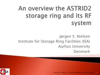
An overview the ASTRID2 storage ring and its RF system. Jørgen S. Nielsen Institute for Storage Ring Facilities (ISA) Aarhus University Denmark. ASTRID2. ASTRID2 is the new synchrotron light source to be built in Århus, Denmark Dec 2008: Awarded 5.0 M€ for

An overview the ASTRID2 storage ring and its RF system
E N D
Presentation Transcript
An overview the ASTRID2 storage ring and its RF system Jørgen S. Nielsen Institute for Storage Ring Facilities (ISA) Aarhus University Denmark ESLS-RF 13 (30/9-1/10 2009), ASTRID2 and its RF system
ASTRID2 • ASTRID2 is the new synchrotron light source to be built in Århus, Denmark • Dec 2008: Awarded 5.0 M€ for • Construction of the synchrotron • Transfer of beamlines from ASTRID1 to ASTRID2 • New multipole wiggler • We did apply for 5.5 M€ • Cut away an undulator for a new beamline • Has to be financed together with a new beamline • Saved some money by changing the multipole wiggler to better match our need ESLS-RF 13 (30/9-1/10 2009), ASTRID2 and its RF system
ASTRID2 main parameters • Electron energy: 580 MeV • Emittance: 12 nm • Beam Current: 200 mA • Circumference: 45.7 m • 6-fold symmetry • lattice: DBA with 12 combined function dipole magnets • Integrated quadrupole gradient • 4 straight sections for insertion devices • Will use ASTRID as booster (full energy injection) • Allows top-up operation ESLS-RF 13 (30/9-1/10 2009), ASTRID2 and its RF system
ASTRID2 Layout ESLS-RF 13 (30/9-1/10 2009), ASTRID2 and its RF system
ASTRID2 Layout ESLS-RF 13 (30/9-1/10 2009), ASTRID2 and its RF system
ASTRID2 details ESLS-RF 13 (30/9-1/10 2009), ASTRID2 and its RF system
ASTRID2 lattice ESLS-RF 13 (30/9-1/10 2009), ASTRID2 and its RF system
ASTRID2 Status • Sep. 2009: Order of • Magnets on girders for thesynchrotron • Dipoles, Q-poles, Sextupoles,correctors • Fast magnets with power supplies • Extr. Kicker, fast bumpers, inj. Septum • Timeline • -2010: Design and order remaining items • 2011: Build and commission synchrotron • 2012: First beamlines on ASTRID2 • 2013: All beamlines transferred to ASTRID2 ESLS-RF 13 (30/9-1/10 2009), ASTRID2 and its RF system
ASTRID2 RF • 105 MHz (like ASTRID) • Main RF parameters • Harmonic: 16 • RF voltage: 50-150 kV • Synchrotron frequency: 10-17 kHz • Synchrotron radiation power: ~1.4 kW • Cavity power: 0.8-7 kW • 10 kW tube-based FM transmitter (triode) • Tube-based FM transmitters are • Cheaper • More robust ESLS-RF 13 (30/9-1/10 2009), ASTRID2 and its RF system
ASTRID2 Cavity • Collaboration with MAX-lab • MAX-lab needs 8 cavities (100 MHz) for MAX IV • We need 2 cavities (105 MHz) (a spare for ASTRID1) • New MAX-lab cavity • Based on MAX II cavity • Use Electron Beam Welding instead of vacuum brazing • Proposal: Have industry build after MAX-lab RF design • MAX-lab will also build a 300 MHz Landau cavity ESLS-RF 13 (30/9-1/10 2009), ASTRID2 and its RF system
New ASTRIDx LLRF • We will need a new LLRF for ASTRID2 • The present ASTRID LLRF is • Old, Analog • Risk of failure, not easy to repair/maintain • We are seeking a solution which is • Simple (we have limited resources) • Adequate • Two possibilities • Fully digital: • Direct digital sampling of down converted signals • Others achieve 0.1% stability • Analog down conversion to baseband • Digital control of baseband signals • Stability: ~1% ESLS-RF 13 (30/9-1/10 2009), ASTRID2 and its RF system
ASTRIDx LLRF (proposal) • Digital control of baseband signal • Either with IQ modulators and demodulators or with amplitude and phase • A computer (PC) running LabVIEW Real-Time with FPGA equipped multifunction card to measure and control the baseband signals • NI PCIe-7851R/7852R: • Virtex 5 FPGA, 8 AI, 750 kS/s/ch, 8 AO, 1 MS/s/ch, 16 bit • PID Loop rates in excess of 100 kHz • Cavity fill time has a 3 dB point at 6 kHz • We believe this solution is • Simple, but adequate • Flexible • Allows easily integrated diagnostics ESLS-RF 13 (30/9-1/10 2009), ASTRID2 and its RF system
Combiner Atten- nuator Phase shifter -5 – -55 dB -180° – +180° DM2 DM1 Dx MO MO ASTRIDx LLRF proposal Master oscillator 104.95 MHz Rohde&Schwarz SMY01 or DDS optional Fast feedback loop FM transmitter +36 dB, 10 kW PreAmp +40 dB, 10 W Attenuator/ gain Phase shifter -33 – +25 dB -180° – +180° RF splitter Splitter Dx adcMOlevel dacPlunger adcFPWQ adcCavQ adcFPWI adcRPW adcCavI dacφ dacA Realtime computer with IO (e.g. PC (or an NI Compact RIO) with LabVIEW RealTime) ESLS-RF 13 (30/9-1/10 2009), ASTRID2 and its RF system
Conclusions • Have shown you • The new ASTRID2 SR source • The RF system for ASTRID2 • Proposal for new ASTRIDx LLRF • Would appreciate feedback on our ideas • Analog system (digital control of baseband signals)? • Fully digital system with fast sampling of down converted signal? • Do we need the higher stability? ESLS-RF 13 (30/9-1/10 2009), ASTRID2 and its RF system