Download
1 / 16
160 likes | 303 Views
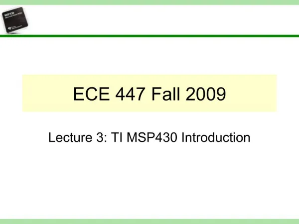
ECE 447 Fall 2009. Lecture 7: MSP430 Polling and Interrupts. Agenda. Polling Introduction to Interrupts Class Example. Main Program. Polling routine. Service device #1. Signal from device #1?. Service device #2. Signal from device #2?. Signal from device #N?. Service

E N D
ECE 447 Fall 2009 Lecture 7: MSP430 Polling and Interrupts
Agenda • Polling • Introduction to Interrupts • Class Example
Main Program Polling routine . . . . . . . Service device #1 Signal from device #1? Service device #2 Signal from device #2? Signal from device #N? Service device #N Cycle continuously ECE447: Polling Concept
ECE447: Loop usage for polling events public void main(void) { …. while ( !(P1IN & BIT0) ) ; // Correct …. } public void main(void) { …. while (P1IN & BIT0) { // Incorrect } …. } Loops can be used to poll events (both internal or external). The two examples on the left show the correct and incorrect usage of polling loops. The first loop holds the program in one spot until the condition evaluates false. The semi-colon is equivalent to a pair of empty brackets (“{ }”). This program will only move past this point once P1.0 is high. The second loop processes its contents as long as the condition is true. This usage is discouraged because the condition could change multiple times while the contents of the loop are executing.
ECE447: Loops in C and Assembly C Assembly ; infinite loops Label1: ; do processing JMP Label1 ; jump always ; blocking loops Label2: BIT.B #BIT0, &P1IN JZ Label2 ; jump if not set ; process input ; complex conditions Label3: BIT.B #BIT0, &P1IN JNZ End_loop ; jump if set BIT.B #BIT0, &P2IN JNZ End_loop ; jump if set JMP Label3 End_loop: ; process input // infinite loops for (;;) { // or while(1) { // do processing } // blocking loops while ( !(P1IN & BIT0) ); // process input // complex conditions while ( !(P1IN & BIT0) && !(P2IN & BIT0) ); // process input
Interrupt Applications • Urgent Tasks with a Higher priority than the main code • Infrequent tasks (handling slow input from humans) • Waking the CPU from Sleep • Calls to an operating system
Interrupt Features • Interrupts can be requested by most peripherals and some core MCU functions • Each interrupt has a flag • This flag is “raised” (set) when the condition for the interrupt occurs • Each flag has a corresponding ENABLE bit which allows interrupt requests • Maskable Interrupts • Effective only if the General Interrupt Enable (GIE) bit is set in the Status Register
ECE447: MSP430 Interrupts Overview • Interrupt processing • Program Counter (PC) is stored on the stack • Status Register (SR) is stored on the stack • Interrupt flag is cleared • SR is cleared • GIE = 0, disables interrupt • Low power modes cancelled • PC is set to the calling interrupts vector value (e.g. value stored at 0xFFFC for NMI)
ECE447: Interrupt Trigger Types (Level/Edge) Interrupt on high level Level Sensitive: Interrupt triggers as long as the source is at certain level (high or low). Edge Sensitive: Interrupt triggers when the source changes from one state to another (high to low, low to high, or both) Note: The MSP430 offers only edge sensitive interrupts, and only one edge may be detected at a time. Rising Edge Falling Edge Both Edges
ECE447: MSP430 Reset Overview • There are two levels to the RESET interrupt • Power-on Reset (POR) • Power on (or brownout without SVS) • Low signal on the /RST pin • Power-up Clear (PUC) • Watchdog timer overflow • Incorrect Watchdog password • Incorrect flash memory password • Fetch from reserved/unimplemented memory • Status after RESET • Status Register (SR) cleared (low power modes cancelled) • Register and peripheral defaults initialized • rw-0: bit reset to zero after PUC or POR • rw-(0): bit reset to zero only after POR (rw = read/write) • Program Counter (PC) set to value stored at 0xFFFE (the reset vector)
ECE447: Class Exercise Write a routine in assembly that polls the P1.1 input pin of the MSP430 for the status of a button. As long as the logic signal on that pin remains high the MSP430 will output the pattern ‘0101’ on pins P1.4 to P1.7. When the button is released the output will invert to ‘1010’. This behavior should repeat indefinitely when the button is pressed and released.
Summary • Polling • Introduction to Interrupts • Class Example