Download
1 / 3
0 likes | 10 Views
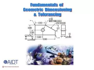
Geometric Dimensioning and Tolerancing Course Outline

E N D
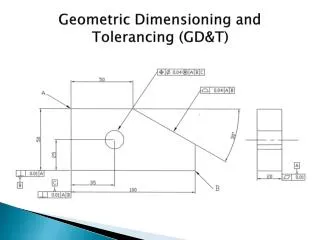
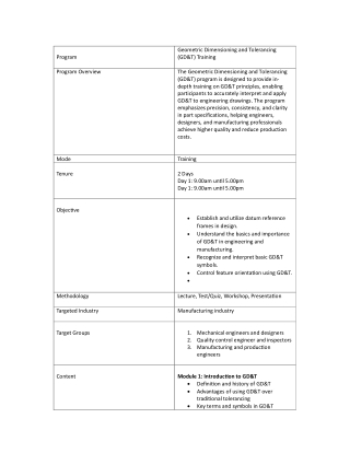
Program Geometric Dimensioning and Tolerancing (GD&T) Training The Geometric Dimensioning and Tolerancing (GD&T) program is designed to provide in- depth training on GD&T principles, enabling participants to accurately interpret and apply GD&T to engineering drawings. The program emphasizes precision, consistency, and clarity in part specifications, helping engineers, designers, and manufacturing professionals achieve higher quality and reduce production costs. Program Overview Training 2 Days Day 1: 9.00am un?l 5.00pm Day 1: 9.00am un?l 5.00pm Mode Tenure Objec?ve Establish and u?lize datum reference frames in design. Understand the basics and importance of GD&T in engineering and manufacturing. Recognize and interpret basic GD&T symbols. Control feature orienta?on using GD&T. Methodology Lecture, Test/Quiz, Workshop, Presenta?on Manufacturing industry 1.Mechanical engineers and designers 2.Quality control engineer and inspectors 3.Manufacturing and produc?on engineers Module 1: Introduc?on to GD&T Defini?on and history of GD&T Advantages of using GD&T over tradi?onal tolerancing Key terms and symbols in GD&T Targeted Industry Target Groups Content
Standards (ASME Y14.5, ISO) Module 2: Basic symbols and Defini?ons Datum features and datum reference frame Geometric characteris?cs symbols (form, orienta?on, loca?on and runout) Feature control frames and understanding tolerance zones Module 3: Datums and Datum references Frames Datum reference frame setup for part loca?on Iden?fying primary, secondary and ter?ary datums. Module 4: Form Tolerances Straightness, flatness, circulatory and cylindricity. Tolerance zone shapes for form control Real world applica?on and part inspec?on methods Exercises in assigning and interpre?ng form tolerances. Module 5: Orienta?on Tolerances Angularity, perpendicular, and parallelism Establishing angular control between features Differences and rela?onship with form tolerances Module 6: Loca?on Tolerances Posi?onal tolerancing and tolerance zones Concentricity, symmetry, and related concepts True posi?on and its benefits for hole pa?erns and key features Module 7: Profile and Runout Tolerances Surface profile and line profile tolerances Circular and total runout tolerances Applica?ons for complex surface controls
Module 8: Applica?on, Inspec?on and Measurement Tolerance stacking and analysing part fit GD&T inspec?on methods (CMMs, gauges, manual methods) Common challenges and best prac?ces Final project: GD&T applica?on on a sample part drawing Module 9: Advanced Tolerancing Concepts Bonus tolerance concepts and how they benefit designs Virtual condi?on and func?onal gauging Analyzing tolerance stacking and its impact on design Module 10: GD&T Applica?on in Industry and Final Project GD&T best prac?ces and common challenges in industry Case studies from aerospace, automo?ve, and manufacturing Final project: Apply GD&T principles to a sample part drawing, including inspec?on and repor?ng