Download

1 / 16
200 likes | 561 Views
Geometric Dimensioning and Tolerancing. Chapter 1, Introduction. History. during the early period of manufacturing there were seldom any drawings one-off manufacturing ~1798 – concept of interchangeable parts

E N D
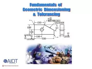
Geometric Dimensioning and Tolerancing Chapter 1, Introduction
History • during the early period of manufacturing there were seldom any drawings • one-off manufacturing • ~1798 – concept of interchangeable parts • Eli Whitney won a contract to supply musketsto the United States government. The firearmsmanufacture were based on the concept ofinterchangeable parts. • He made a presentation to congress by building10 guns and assembling and disassemblingthem claiming the same exact parts andmechanisms. • specifying tolerances became veryimportant Eli Whitney 1765 - 1825
Tolerances • All dimensions require a tolerance. • A tolerance should be as large as possible without interfering with the function of the part to minimize production costs. • Consider how your part will be checked to see if it meets the tolerances.
Plus/Minus (Limit) Tolerancing • Plus/minus tolerancing seemed to work well for many applications.
Limit Tolerancing • Is the .620-.630 hole horizontal position measured from a true vertical plane or from the as built face? • A .005” tolerance on the horizontal and vertical position of the hole means that the position could be off by as much as.007”. max allowed error for hole center .007 +.005 perfect location for hole center +.005
Limit Tolerancing • Limit tolerances don’t have an origin or any orientation or location relative to datums. • The datums are usually implied. • The drawings are subject to different interpretations. • Plus/minus tolerancing works well for individual features of size (ex. diameter of a shaft), but does not control the relationship between individual features very well.
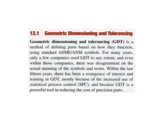
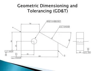
GDT • Limit tolerancing can give the size of individual features. • GDT can provide: • relationships between features • circular tolerance zone for hole placement • GDT removes any ambiguity from the drawing specification
History of Dimensioning and Tolerancing Standards in the USA Mil Std 8 1950’s Mil Std 8A Mil Std 8B Mil Std 8C-1963 ASA-Y14.5-1957 USASI Y14.5-1966 ANSI Y14.5-1973 ANSI Y14.5M-1982 ASME Y14.5M-1994 ASME Y14.5-2009
Geometric Dimensioning and Tolerancing (GDT) • establish a reference coordinate system by defining datums • provide basic dimensions (perfect dimensions) relative to the datums • specify allowable tolerances
communication symbols ASME clarity replace total form size & location function & relationship tolerance tolerances & interchageability plus/minus size