PREFORMS - PReform Engineering using Forward and Reverse Modeling Simulation
PREFORMS - PReform Engineering using Forward and Reverse Modeling Simulation. Deformation Control Technology, Inc. and Wright State University. Features. A reverse forming simulation software tool. A true design tool not just a simulation tool.

PREFORMS - PReform Engineering using Forward and Reverse Modeling Simulation
E N D
Presentation Transcript
PREFORMS - PReform Engineering using Forward and Reverse Modeling Simulation Deformation Control Technology, Inc. and Wright State University
Features • A reverse forming simulation software tool. • A true design tool not just a simulation tool. • Incorporates reverse simulation and optimization. • UNIX and PC platforms. • Works with DEFORM from Scientific Forming Tech. Corp. • Continued development and support by WSU and DCT. • Customer support availability .
Features • Capable of both forward and backward material deformation simulations. • Simulates plane strain and axisymmetric forging shapes • Friendly graphical user interface. • Capable of producing detailed deformation information under combined mechanical and thermal loading. • Solves a large variety of problems by suitably altering the model process parameters. • Ability to quantitatively predict metal flow using FEM
PREFORMS Benefits • Design preform die shapes to achieve complete die fill. • Reduce material waste, i.e. achieve a net shape forging process by optimizing material utilization and minimize flash. • Eliminate surface defects, i.e. laps and voids. • Eliminate internal defects, i.e. shear cracks and poor microstructure. • Minimize effective strain and strain-rate variance in workpiece. • Design optimal process parameters such as forming rate (die velocity) as well as initial workpiece and die temperatures.
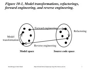
PREFORMS General Flowchart showing overview of PREFORMS program
Design Goals Die Shape Optimization: • Number of preform stages • Preform shapes Optimal Forging Process Parameters: • Press velocity profile • Die and billet temperatures Optimal Process Constraints: • More uniform strain, strain-rate and temperature distributions • Eliminate localized deformations • Eliminate forging defects and cavities
Methodologies Two distinct design strategies for preform design: • Backward Tracing Method • Numerical Optimization Method
Backward Tracing Method • Starts with final shape (die filled). • Simulation is conducted in reverse. • Preform shape evolves as material is released from dies. • Path is not unique. • Requires boundary node detachment criterion • Resulting shape depends on the detachment criteria used.
Backward Tracing Method • Divide die surfaces into a number of straight line or arc segments. • Record the time at which each die segment comes into contact with the workpiece during the forward simulation with a trial preform shape. • Modify the recorded time sequence if the trial preform does not satisfy the design objectives. • Die fill requirements • Flash size requirements • Material flow characteristics • The modified contact time sequence is then used as the boundary node detachment criterion for the backward deformation simulation.
Modification Guidelines Multi-Cavity Forging: • Contact time of earliest filled cavity is reduced to allow all cavities to be filled at the same time. Underfilled Cavity: • Contact time of underfilled die segment is defined as time of final stroke. Contact times of adjacent die segments are reduced to the closest die segment where time is defined.
Modification Guidelines Cavity-Fill Before Final Stroke: • Contact times of all die segments reduced by same value. Value is the difference between the final stroke and the time at fill. Large Flash: • Contact time for outermost die segments (flash) is the time at which upper die is at required final position.
Turbine Disk Preform Design Material flow patterns during backward simulation of final forging stage. Preform shape (most of the die contact nodes are detached)
Turbine Disk Preform Design Forward verification of blocking stage using blocker designed by backward simulation. Blocker filled
Turbine Disk Preform Design Forward verification simulation of generic turbine disk.
Numerical Optimization Method • Nonlinear sensitivity analysis of plastic deformation. • End goals are achieved with defined flow requirements. • Preform shape is optimized using B-splines. • Iteratively optimized using forward simulations. • Method is very general and applicable to other unit processes.
Optimization Variables Spline Control Points as Optimization Variables
Iterative History Iteration 1 2 3 4 5 6 Optimum Evolution of Preform Shape During the Design Search
Optimal Forging Sequence - 1 Starting Billet for Stage I Operation Final Forging for Stage I Operation
Optimal Forging Sequence - 2 Stage I Forging Transferred to Stage II Dies Stage II Final Forging using Stage I Preform (Eff. Strain Variance = 1.26)
Dr. Ramana Grandhi Professor Wright State University Dr. Zhichao (Charlie) Li Dr. B. Lynn Ferguson Mr. Greg Petrus Mr. Andrew Freborg Deformation Control Technology, Inc. Personnel
Future Directions Increase robustness of sensitivity analysis • Continue excellent work started and continuing at Wright State and now Deformation Control Technology 3 Dimensional Capability • Dr. Grandhi has been investigating 3D Added dimension of DCT • DCT is now combining their industrial skills and successes with the academic excellence of WSU to make PREFORMS a reality.
Contact Information • Visit the web at www.DeformationControl.com. Deformation Control Technology, Inc. 7261 Engle Road, Suite 105 Cleveland, OH 44130 Phone: 440-234-8477 Fax: 440-234-9140
A commercial finite element based software tool for heat treating • State-of-the-art mechanical and transformation kinetics models • Accurate description of heat transfer during heating and cooling steps • Validated carburization model • Addresses immersion quenching, intensive quenching methods, gas quenching and press quenching
DANTE/KIVATM Capabilities • Design Tool Results • Carburization • Microstructural Phases • Residual Stress • Dimensional Change
DANTE/KIVA Additional Benefits: • - User’s Group Participation- Material / Process Database- Development Participation- Local Technical Support/Customer Service • DCT - Cleveland, Ohio • NRS Associates - Hartford, CT • MLC Technical Consulting - Livermore, CA • Sierra Vista Technology - Albuquerque, NM
TYPICIAL PARTS MODELED IN DANTE/KIVA SYSTEM Complex Gear Shapes Shafts Coil Springs
Carburization Heat Transfer Methodology Kinetics Models & Databases Mechanics Model & Databases Meshing Templates Residual Stresses Microstructure Dimensional Changes DANTE™ - Approach to Analysis