Download
1 / 25
250 likes | 381 Views
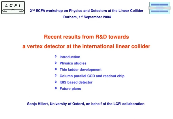
A vertex detector for the next linear collider. Stefania Xella on behalf of the LCFI collaboration: Bristol Univ., Lancaster Univ., Liverpool Univ., Oxford Univ., Rutherford Appleton Laboratory, Queen Mary University London hep.ph.liv.ac.uk/~green/lcfi/home.html.

E N D
A vertex detector for the next linear collider • Stefania Xella • on behalf of the LCFI collaboration: • Bristol Univ., Lancaster Univ., Liverpool Univ., Oxford Univ., Rutherford Appleton Laboratory, Queen Mary University London • hep.ph.liv.ac.uk/~green/lcfi/home.html S.Xella – Rutherford Appleton Laboratory
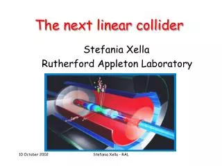
Next Linear Collider: a challenging environment for a vertex detector • Main goal of the next linear collider is to measure PRECISELY the Higgs boson and possibly physics beyond the SM. This requires: • High energy and luminosity, which might mean • high beam background: • Tesla: 50 ms = 4 backgr hits/mm2 at 15 mm radius • => fast detector readout • Optimal jet/flavour reconstruction due to event topology • ee->tt : 6 jets, 2 b and 2 c flavoured • ee->HA : 12 jets, 4 b flavoured • => very granular, low material budget detector S.Xella – Rutherford Appleton Laboratory
Importance of the right design optimal vertex detector design is most important, to reach final physics goal ! PRELIMINARY tagging purity vs efficiency 5 layers, 0.1%X0 4 layers, 0.2%X0 S.Xella – Rutherford Appleton Laboratory
LCFI collaboration • Linear Collider Flavour Identification collaboration R&D work concentrates on a CCD pixel device : Mechanical support (RAL PPD/Oxford) CCD development design/test (RAL PPD/E2V/ Liverpool) design optimization from physics (see T.Kuhl talk) (RAL PPD/Bristol/Lancaster) Readout IC, Driver IC, … (RAL ME/Oxford) S.Xella – Rutherford Appleton Laboratory
Current design (I) • Small pixels (20x20 mm2) • -> precise point resolution • thin detector(<0.1%X0) • -> less multiple scattering • close to the IP (15 mm) • -> smaller extrapolation • error • large polar angle coverage • |cos()|<0.90 with 5 hits • |cos()|<0.96 with 3 hits S.Xella – Rutherford Appleton Laboratory
Current design (II) • 5 layers • -> higher resolution • -> robust local alignment • -> effective gamma conversion • fast readout (50s/layer) • -> sustain high integrated • background • gas cooled, low mass foam • cryostat • minimal electronics (power + • few optical fibres) • -> little material at low angles S.Xella – Rutherford Appleton Laboratory
Detector VXD2 VXD3 Future LC 480 96 120 1.2 12.8 27.5 120 307 799 CCDs 2 3 5 28 28 15 1.1 0.4 0.06 CCD active area 0.75 0.90 0.96 Number of pixels 160 ms 216 ms 50/250 (8 ms for NLC) Effective no. of layers Inner layer radius (mm) Layer thickness () (2-hit) Imp. param resoln. Readout time Very challenging ! S.Xella – Rutherford Appleton Laboratory
N N “Classic CCD” Readout time NM/Fout Column Parallel CCD Readout time = N/Fout Column Parallel CCD (CPCCD) • Fast readout speed only with Column parallel readout new design! • Serial register omitted • 50 Mpixels/sec from each column • Image section clocked at high frequency • Each column has its own ADC/amplifier M S.Xella – Rutherford Appleton Laboratory
Readout chip (CPR) • CMOS circuit bump bonded to the CCD • Each column has amplifier and ADC • Correlated double sampling for low noise • Sparsification done in the chip • Buffer memory and I/O interface S.Xella – Rutherford Appleton Laboratory
Ladder end • Bump bonding CPCCD-CPR • Driver IC provides high frequency (50MHz), low voltage (1.5V pp) clocks • 2-phase driven CCD • Low inductance connections and layout • Small clock and digital feedthrough S.Xella – Rutherford Appleton Laboratory
Device simulations • ISE-TCAD software used at RAL. Mostly important: • To check feasibility of current design • Foresee show-stoppers • Test new ideas S.Xella – Rutherford Appleton Laboratory
Status of R&D program • 5 or 6 stage R&D program in collaboration with E2V (former Marconi Applied Technology) company in the UK • Test for high speed CCD readout (up to 50MPix/sec) successfully carried out on standard CCD58 device, in serial register • Test for radiation damage at different temperatures/RO frequency being carried out • CPCCD-1 and CPR-0,1 are (being) produced. • Testing during end2002/beg2003 • Several options for mechanical support design currently investigated (unsupported/semi-supported) S.Xella – Rutherford Appleton Laboratory
Standard 2-phase implant Field-enhanced 2-phase implant (high speed) Metallised gates (high speed) Metallised gates (high speed) 2-stage source followers Source followers Source followers Direct Direct Readout ASIC Readout ASIC To pre-amps First CPCCD-CPR • 2 different charge transfer regions • 3 types of output circuitry • Independent CPCCD and CPR test possible • Designed to work in almost any case! S.Xella – Rutherford Appleton Laboratory
First CPR tests • 0.25 mm CMOS • Charge transfer amplifier (CTA) in each ADC comparator • Designed to work up to 50 MHz • First CPR produced: small chip (2x6mm), testing flash ADC and voltage amplifiers. Very promising results. • Next CPR contains CTA,ADC,FIFO memory in 20 mm pitch S.Xella – Rutherford Appleton Laboratory
Tests of high speed CCD • E2V CCD58 • 3-phase driven CCD • Classical readout • (serial register) • 12 m 2 pixels • 2 outputs • 2x106 pixels in two sections S.Xella – Rutherford Appleton Laboratory
Tests of high speed CCD • 55Fe X-ray spectrum at 50 Mpix/s • MIP-like signal (5.9 keV X-rays generate 1620 electrons) • Low noise 50 electrons at 50 MHz clocks • CCD58 is designed to work with large signals at 10 Vpp clocks • No performance deterioration down to 5 Vpp clocks • Still good even at 3 Vpp clocks S.Xella – Rutherford Appleton Laboratory
low drive voltage/CTI Clock traces and 55Fe spectrum for low drive voltages at 50 Mpix/sec • Radiation damage effects: • beam background expected • about 50krad/year • (neutron 5x10⁹/cm2/year) • CTI should improve at fast • readout : to be verified • CCD58 can be flexibly clocked from 1 to 50 MHZ, so it should be possible to obtain good results for CTE S.Xella – Rutherford Appleton Laboratory
Mechanical support R&D • Final goal is to design a CCD support structure with • Low mass (< 0.1% Xo) • Stable shape under repeated temperature cycles down to –100oC • Minimum metastability and hysteresis effects • Compatible with bump bonding • Robust assembly • Able to undergo gentle gas cooling S.Xella – Rutherford Appleton Laboratory
Thin ladder options • Unsupported CCD : thinned to 50 mm and held under tension. Tested experimentally: • * sagitta stability found better than 2 mm at T>2N, but • * large differential contraction at CCD surface causes lateral curling + design is difficult to handle • Semi-supported CCD :thinned to 20 mm and attached to thin (not rigid) Be support, held under tension. Tested in ANSYS simulation: • * CCD surface may become dimpled: under study • * may need fine pitched matrix of glue: difficult? • => still lots of work to do and ideas to test S.Xella – Rutherford Appleton Laboratory
Thin ladder options CCD (20 μm thin) bonded with adhesive pads to 250 μm Be substrate On cooling adhesive contracts more than Be pulls Si down on to Be surface Layer thickness 0.12% Xo 1 mm diameter adhesive columns inside 2 mm diameter wells 200 μm deep in Be substrate S.Xella – Rutherford Appleton Laboratory
Summary • The LCFI collaboration R&D program is • vast, and very challenging. • Its aim is to provide a • fast and low material budget CCD based pixel detector • to maximize the physics potential of the next linear • collider • We are only at the first stage of a long R&D program, so stay tuned to hear more ! S.Xella – Rutherford Appleton Laboratory
Backup slides S.Xella – Rutherford Appleton Laboratory
Backgrounds at the nlc S.Xella – Rutherford Appleton Laboratory
Wire/bump bond pads Charge Amplifiers Voltage Amplifiers 250 5-bit flash ADCs FIFO Bump bond pads CPR-1 In CPR-1: • Voltage amplifiers – for source follower outputs from the CPCCD • Charge amplifiers – for the direct connections to the CPCCD output nodes • Amplifier gain in both cases: 100 mV for 2000 e- signal • Noise below 100 e- RMS (simulated) Direct connection and charge amplifier have many advantages: • Eliminate source followers in the CCD • Reduce power 5 times to 1 mW/channel • Programmable decay time constant (baseline restoration) ADC full range: 100 mV, AC coupled, Correlated Double Sampling built-in (CTA does it) S.Xella – Rutherford Appleton Laboratory
Semi-supported silicon Carbon fibre support Aerogel support Carbon fibre: CTE is tunable, layers can have optimal orientation and fibre diameter, difficult to simulate Aerogel support: chemically bonds to Si, aerogel in compression Many other ideas:CVD diamond, vacuum retention, etc… S.Xella – Rutherford Appleton Laboratory