Download
1 / 54
540 likes | 731 Views
OPTIMIZATION OF CONVENTIONAL THERMAL & IGCC POWER PLANT FOR GREEN MEGA POWER. Dr. V K Sethi & J K Chandrashekar Director Adviser University Institute of Technology

E N D
OPTIMIZATION OFCONVENTIONAL THERMAL & IGCC POWER PLANT FOR GREEN MEGA POWER Dr. V K Sethi & J K Chandrashekar Director Adviser University Institute of Technology RGTU Bhopal
WORLD SUMMIT ON SUSTAINABLE DEVELOPMENT AGENDA FOR THE ENERGY GENERATION SECTOR: • Increased use of Advanced Fossil Fuel Technology. • Promote CCT in countries where coal is main stay fuel for Power Generation. • Reduce Atmospheric Pollution from Energy Generating Systems. • Enhance productivity through Advanced Fossil Fuel Technology. • Adoption of Renewable Energy Technologies in Rural Sector
INDIAN POWER SECTOR JOINS TERA CLUB BY 2010 • POWER GENERATION BY UTILITIES TODAY 1,47,965 MW …600 Billion kWh per annum • TARGETTED CAPACITY ADDITION BY XI PLAN END • Central 46,500 MW • State & IPP 41,800 MW • NCES 10,700 MW • Nuclear 6,400 MW Total 105,400 MW • BY 2012 WE NEED TO GENERATE ANNULLY …Over 1000 Billion kWh • THUS WE WILL BE A TRILLION or TERA kWh (Unit) GENERATING POWER SECTOR BY 2012
Tera-watt Challenge for synergy in Energy & Environment • A terawatt Challenge of 2012 for India To give over one billion people in India the minimum Electrical Energy they need by 2012, we need to generate over 0.2 terra watt (oil equivalent to over 3 million barrels of oil per day) and 1 TW by 2040,primarily through Advanced fossil fuel technologies like CCTs for limiting GHG emission levels • By 2020 our mix of generation would have the Peak in Thermal, certainly it would be theGreen Thermal Power: • Thermal 326,000MW • Renewable & Hydro 104,000 MW • Nuclear 20,000 MW • Total 450,000 MW
POWER SCENARIO IN INDIA Installed capacity in Utilities as on April 07 …1, 47, 965 MW • Thermal Installed Capacity…93,726 MW (Coal 77,648 MW, Gas 14,876 MW, Diesel 1202 MW + Others- cogen etc.) • Hydro Power …36,877 MW • Nuclear Power … 4120 MW • Renewable Energy Sources …13,242 MW • Electric Demand…..7-8% growth • Peak & Energy Shortage…..16.7% & 12.1% • Capacity Addition in 11th Plan……80,020 MW
INDIANPOWER SECTOR - TOWARDS SUSTAINABLE POWER DEVELOPMENT • Total Installed Capacity … 1,47,965 MW • Thermal Generation … over 66 % • Although no GHG reduction targets for India but taken steps through adoption of Renewable Energy Technologies,Combined cycles, Co-generation, Coal beneficiation,Plant Performance optimization • Under Kyoto Protocol; Clean Development Mechanism (CDM) conceived to reduce cost of GHG mitigation, while promoting sustainable development as per Framework Convention on Climate change (FCCC)
Prime Clean Coal Technology Options • Supercritical Power Plants • Integrated Gasification Combined Cycle (IGCC) Power Plants • Circulating Fluidized Bed Combustion (CFBC) Power Plants
FRONTALS IN ENERGY & ENVIRONMENT • GREEN ENERGY TECHNOLOGIES – PRIMARILY THE CLEAN COAL TECHNOLOGIES • ZERO EMISSION TECHNOLOGIES FOR TRANSPORT, POWER PLANTS & INDUSTRIAL SECTOR • AFFORDABLE RENEWABLE ENERGY TECHNOLOGIES • ENERGY EFFICIENCY • CDM OPPORTUNITIES IN ENERGY SECTOR
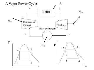
Optimization of Prime Performance Functions- Heat Rate & Boiler Efficiency • Heat Rate – The Heat supplied to Steam in Boiler for producing one kWh • MATHEMATICAL MODELING The mathematical models for the plant performance can be divided into two main categories 1. Basic Models: These consist of (a) Steam table model. (b) Combustion model –total approach to combustion of PF. (c) Wet steam expansion model. (d) Boiler heat transfer model for radiation and other unaccountable losses 2. Specific models • Boiler accountable losses based on fuel characteristics. • Mill operation window. • Unburnt Carbon • Turbine heat rate. • Cylinder efficiency. • Condenser performance. • Feed heaters. • Overall unit heat rate model.
IGCC (Integrated Gasification Combined Cycle) The IGCC process is a two-stage combustion with cleanup between the stages. • The first stage employs the gasifier where partial oxidation of the solid/liquid fuel occurs by limiting the oxidant supply. • The second stage utilizes the gas turbine combustor to complete the combustion thus optimizing the gas turbine/combined cycle (GT/CC) technology with various gasification systems.
IGCC (Integrated Gasification Combined Cycle) • The Syn-Gas produced by the Gasifiers however, needs to be cleaned to remove the particulate, as well as wash away sulphur compounds and NOx compounds before it is used in the Gas Turbine. • It is the Integration of the entire system components, which is extremely important in an IGCC Plant. • Various sub-systems of an IGCC Plant thus are: i) Gasification Plant ii) Power Block iii) Gas Clean-up System
o Super Critical PC Power Plant (15 C Amb.) 60 Super Critical PC Power Plant (Indian Condition) o IGCC (15 C Amb) 55 IGCC (Indian Condition) Sub Critical PC Power Plant (Indian Condition) 50 o 1500 C o 1300 C o 623 C Net Thermal Efficiency (%) o 600 C 45 o 566 C 40 Ceramic gas turbine o 1184 C o 650 C 35 o 540 C 30 1995 2000 2005 2010 1990 Year of commercial use EFFICIENCY IMPROVEMENT FORECAST CONVENTIONAL Vs IGCC
Steam to Super Heater Cyclone Back-Pass Coal Feed Hopper Furnace ESP External Heat-Exchanger Ash Cooler HP Air Circulating Fluidized Bed Boiler
Coal Gasification • Combustion Process: Excess Air • Gasification Process: Partial Combustion of coal with the controlled oxygen supply (generally 20 to 70% of the amount of O2 theoretically required for complete combustion) C + 1/2 O2gasification CO C + H2O gasification CO + H2
Flexibility to accept a wide range of fuels • IGCC technology has been proven for a variety of fuels, particularly heavy oils, heavy oil residues, pet-cokes, and bituminous coals in different parts of the globe. In fact the same gasifiers can handle different types of fuels. Environment Friendly Technology • IGCC is an environmentally benign technology. The emission levels in terms of NOx, SOx and particulate from an IGCC plant have been demonstrated to be much lower when compared to the emission levels from a conventional PC fired steam plant. In fact, no additional equipment is required to meet the environment standards.
Lower Heat Rates & Increased Output • The heat rate of plants based on IGCC technology are projected to be around 2100 kcal/kWh compared to 2500 kcal/kWh for the conventional PC fired plants
Gas Clean-up System • The typical steps for Gas Clean-up System aim at particulate removal, sulfur removal and NOx removal. This is achieved as follows: • Particulate Removal: Combination of Cyclone Filters & Ceramic candle Filters • SOx & NOx removal: Combination of steam/water washing and removing the sulfur compounds for recovery of sulfur as a salable product. Hot Gas Clean-Up technology is currently under demonstration phase. Wet scrubbing technology, though with a lower efficiency, still remains the preferred option for gas clean-up systems in IGCC.
Sulfur Removal • Sulfur from the hot fuel gas is captured by reducing it to H2S, COS, CS2 etc. The current sulfur removal systems employ zinc based regenerative sorbents (zinc ferrite, zinc titanate etc.) Such zinc based sorbents have been demonstrated at temperatures up to 650 0C. • Sulfur is also removed by addition of limestone in the gasifier. This is commonly adopted in air-blown fluidized bed gasifiers. • In fact, in the case of Air Blown Gasifiers, sulfur is captured in the gasifier bed itself (above 90%) because of addition of limestone. The sulfur captured in the bed is removed with ash.
Overall Efficiency of IGCC System sys = con x { gt ( 1- sc ) (1 – Hbp) + sc } x gen Where: sys = overall efficiency of the IGCC system con = fuel conversion efficiency gt = Gas turbine cycle efficiency sc = steam cycle efficiency Hbp = heat by-pass ratio (0< Hbp<1) gen = generator efficiency