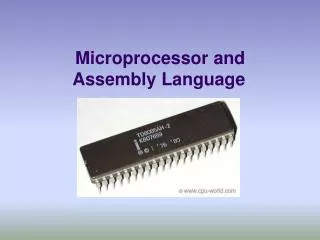
Microprocessor Operation Modes and Memory Addressing
Learn about microprocessor operation modes including Real Address, Protected, and Virtual-8086 modes, as well as IA-32 memory management in real and protected modes. Understand segment and offset addressing, default registers, and how memory is accessed in protected mode.


Microprocessor Operation Modes and Memory Addressing
E N D
Presentation Transcript
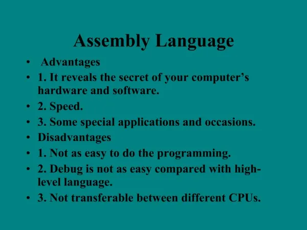
Operation Modes • 80286 processor and above have four operating modes: • Real-address mode: • This mode lets the processor to address "real" memory address. • It can address up to 1Mbytes of memory (20-bit of address). • The first 1 Mbytes of memory is called the real memory, conventional or DOS memory • It also be called "unprotected" mode since operating system (such as DOS) code runs in the same mode as the user applications. • The processor is set to this mode following by a power-up or a reset and can be switched to protected mode using a single instruction.
Operation Modes • Protected mode: • Let the processor address 4GBytes of virtual memory (32-bit address) • Preferred mode for a modern operating system (ex. Windows) • Use virtual memory and provide protections. • System management mode • This mode is designed for fast state snapshot and resumption • It is useful for power management • Virtual-8086 mode: • Allows the processor to execute 8086 code software in the protected, multi-tasking environment.
IA-32 Memory Management • Flat model • Memory appears to a program as a single, continuous address space, called a linear address space. • Code (a program’s instructions), data, and the procedure stack are all contained in this address space • The linear address space is byte addressable, with addresses running contiguously from 0 to 2 32 - 1. • Real-address mode • Backward compatible with 8086 • Memory appears to a program as a group of independent address spaces called segments • Code, data, and stacks are typically contained in separate segments
IA-32 Memory Management • Protected Mode Memory Addressing • Protected mode memory addressing (80286 and above) allows access to data and programs located above the first 1M byte of memory, as well as within the first 1M byte of memory. • Protected mode is where Windows operates. • Paging Model • Memory divided into pages with same size (4k byte) • The linear (Virtual) address is defined as the address generated by a program is translated to the physical address which is the actual memory location accessed by a program
Real-address Mode • Each segment of memory is 64K in length • To access a memory location a combination of a segment address and an offset address are used • segment address defines the beginning address of any 64K-byte memory segment • offset address selects any location within the 64K byte memory segment
Accessinga memory location • The offset address is always added to the segment starting address to locate the data. • Segment and offset address is sometimes written as 1000:2000. – A segment address of 1000H; an offset of 2000H • In the real mode, each segment register is internally appended with a 0H on its rightmost end. • Once the beginning address is known, the ending address is found by adding FFFFH. • because a real mode segment of memory is 64K in length
Default Segment and OffsetRegisters • The microprocessor has rules that apply to segments whenever memory is addressed. • these define the segment and offset register combination • The CS register is always used with the IP to address the next instruction in a program, this combination is CS:IP. • For example, if CS=1400H and IP=1200H, the microprocessor fetches its next instruction from memory location 14000H+1200H= 15200H.
Default Segment and OffsetRegisters • Another of the default combinations is the stack. • stack data are referenced through the stack segment at the memory location addressed by either the stack pointer (SS:SP) or the base pointer (SS:BP) • For example, if SS=2000H and BP=3000H, the microprocessor addresses memory location 23000H for the stack segment memory location.
ProtectedMode Memory Addressing • In place of a segment address, the segment register contains a selector that selects a descriptor from a descriptor table • it selects one of 8192 descriptors from one of two tables of descriptors • The segment register still selects a memory segment, but not directly • The descriptor describes the memory segment’s location, length, and access rights • The offset address can be a 32-bit number instead of a 16-bit number • A 32-bit offset address allows the microprocessor to access data within a segment that can be up to 4G bytes in length.
Selectors • The contents of a segment register during protected mode of the 80286 - Core2 microprocessors.
Descriptors • There are two descriptor tables used with the segment registers: • global descriptors contain segment definitions that apply to all programs • local descriptors are usually unique to an application • ِِِِِA global descriptor might be called a system descriptor, and local descriptor an application descriptor
Descriptors • The 80286 through Core2 64-bit descriptors. Each descriptor is 8 bytes in length,
Descriptors • The base address portion of the descriptor indicates the starting location of the memory segment • The segment limit contains the last offset address found in a segment. For example, if a segment begins at memory location F00000H and ends at location F000FFH, the base address is F00000H and the limit is FFH. • The G bit, or granularity bit. • If G=0, the limit specifies a segment limit • If G=1, the value of the limit is multiplied by 4K bytes (appended with FFFH) • if G=1 This allows a segment length of 4K to 4G bytes in steps of 4K bytes.
Example • Shows the segment start and end if the base address is 10000000H, the limit is 001FFH: • When G=0 • Base = start = 10000000H • End = base+ limit = 10000000H + 001FFH =100001FFH • When G=1 • Base = start = 10000000H • End = base+ limit = 10000000H + 001FFFFFH =101FFFFFH
Descriptors • The AV bit is used by some operating systems to indicate that the segment is available (AV=1 ) or not available ( AV=0) • The D bit indicates if the instructions access register and memory data in the protected or real mode • D=0 the instructions are 16-bit instructions • D=1 the instructions are 32-bit instructions • The access rights byte controls access to the protected mode segment