Machine Language and Assembly Language
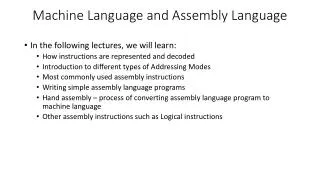
Machine Language and Assembly Language. In the following lectures, we will learn: How instructions are represented and decoded Introduction to different types of Addressing Modes Most commonly used assembly instructions Writing simple assembly language programs

Machine Language and Assembly Language
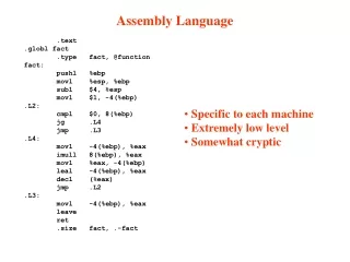
E N D
Presentation Transcript
Machine Language and Assembly Language • In the following lectures, we will learn: • How instructions are represented and decoded • Introduction to different types of Addressing Modes • Most commonly used assembly instructions • Writing simple assembly language programs • Hand assembly – process of converting assembly language program to machine language • Other assembly instructions such as Logical instructions
Instruction Format Reminder: Instruction Interpreter interprets the type of operation, nature of operands (data or address), and mode (memory or register). Overall it interprets the mode of addressing. General format of instruction encoding is: OP: opcode (4 bits) dRn: 3 bits of destination register Om: 3 bits of operation mode or opcode sMS: 6 bits for source Mode Specification: 3 bits for mode and 3 bits for register used Example: Instruction suba a0,a0 encodes into 90C8 in Hex Here opcode is 1001, which stands for a subtraction 000 stands for destination register used is 0 011 indicates destination register used is an address register with word length 001 000 indicates source mode is 001 (mode 1), and source register used is a0.
Instruction Format Another Example: Instruction muls d1,d2 encodes into C5C1 in Hex Here opcode is 1100, which stands for a multiplication 010 stands for destination register used is d2 111 indicates destination register used is always data register 000 001 indicates source mode is 000 (mode 0), and source register used is d1. By Default: instruction operations are on least significant word, therefore the two data are FFFD and 0006. The result of multiplication of two word length data is a longword, the data (-3) is sign-extended to $FFFF FFFD in a working register, before being multiplied by $0006. d1 (source reg) remains unchanged d2 (destination reg) changes to the result value
Instruction Format Another Multiplication Example: muls d3,d0 d3 is source register, and d0 is destination register By Default: instruction operations are on least significant word, therefore the two data are $0073 and $0295. The result of multiplication of two word length data is a longword. Both the data are positive, so no need to sign-extended d3 (source reg) remains unchanged d0 (destination reg) changes to the result value
Effective Address Recall, the address bus for Motorola 68K is 24 bits. Therefore, the memory addresses are 24 bits long. Let the destination be a memory location, and the source be a data register. The instruction in machine language would look something like below: If addresses are explicitly defined as part of the machine language, the instruction becomes too long (2 words instead of 1 word), and accessing the instruction would require more memory accesses. Therefore, Effective Address (EA), which is the address of memory location to be accessed, is not specified in the instruction. Instead, an address register (requires 3 bits to be specified), which contains the EA is used. In other words, address register points to the memory location used. Example: if memory location $0ABCD6 needs to be accessed, then an address register, say a0, should contain $000ABCD6 Now, if we want to access memory location $0ABCD8, we just need to add 2 to a0, and it will point to this new location
Instruction: using Effective Address 8 bits 000000 000001 000002 0ABCD6 0ABCD7 Example: move instruction From Register to Memory location – Mode 2 move d2, (a0) ( ) brackets specify the operand is a memory location Here, EA = [a0], the contents of a0 Suppose a0 = $000ABCD6 (32-bit register) and d2 = $12345678 (32-bit register) The above instruction specifies that the least significant word (lsw) of d2, that is $5678, is moved (copied) to the memory address specified by a0 $56 $78
Another Example: move instruction with displacementMode 5 8 bits 000000 000001 000002 00000C 00000D From Memory location to Register move displ(aj), di move $4(a0), d3 Equivalent Machine instruction is therefore Here, EA = [a0] + sign-ext displacement • sign-extend displacement to 32-bits • Add to the 32-bit contents of a0 • The low-order 24 bits represent the EA Suppose a0 = $0000 0008 (32-bit register) Sign-extended displacement = $0000 0004 Then Effective Address = $0000 000C (consider lower 24-bits) Assume initially d3 = $12345678 (32-bit register) The above instruction moves (copies) the contents of the memory address specified by EA to register d3. After move, d3 = $1234ABCD $AB $CD
Negative displacement Example Since displacement can be negative as represented in 2’s complement form move d3, $FFFC(a0) If a0 = 0000 0008 EA = 0000 0008 (a0) + FFFF FFFC (sign-extended displ) 0000 0004 Therefore, according to the instruction, low-order word of d3 moves to memory location $000004 a0 and d3 remain unchanged.
Memory-to-memory instruction move displ(ai), displ(aj) Here both source and destination have Mode 5. move 164(a0), 6(a1) M[a1 + 6] M[a0 + $A4]
Addressing Modes The addressing modes that we have seen until now are: Mode 0: Data Register Direct addressing Example: move d0, d1 Data size may be byte, word, or longword Mode 1: Address Register Direct Addressing Example: move a0, a1 Because address register specified, valid sizes are word, or longword Mode 2: Address Register Indirect Addressing Example: move d0, (a1) Mode 5: Address Register Indirect Addressing with Displacement Example: move d0, $A(a1) Displacement size is always a word and sign-extended
Micro-instructions for move d3, 2(a0) MAR PC PC MBR M[MAR] IR MBR PC PC + 2 PC points to displacement Decode MBR M[MAR] Displacement loaded MAR A0 + MBR Effective Address calculated MBR D3 Source data moved to memory location given by Effective Address [MAR] MBR PC PC + 2 PC points to next instr. now
Simple Assembly Language program We want to add two 16-bit numbers in memory locations provided consecutively (that is locations X and X+2). Save the result in X+4. We need to first move the data in location X to a data register, say d1 The instruction is therefore of the format move displ(aj), di Now, for us the EA = X Therefore, displ + aj = X If displ = X, then aj = 0 Therefore, our instruction will be move X(a0), d0 with a0 initialized to 0. movea.l #$0, a0 ; a0 initialized to 0, a0 = 0000 0000 move X(a0), d0 ; d0 = ???? 0004 move X+2(a0), d1 ; d1 = ???? 0106 add d1, d0 ; d0 = ????010A move d0, X+4(a0)
Example for Mode 5 (with displacement) a1 The sub-program can be better written as 0000 1000 0000 0020 Offset (displacement) as a constant Offset (displacement in the address register a1 Register a1 is used as the reference point
Another Example for Mode 5 Figure 2.14 from Hamacher book Figure 2.15 from Hamacher textbook Example of using both, Offset as a Constant and Offset in the register Student 1 Test1 Test2 Test3 Student 2 Test1 Test2 Test3 ….. Student nTest1 Test2 Test3 SUM1 SUM2 SUM3 Offset as a constant Offset in a register