Download
1 / 31
310 likes | 442 Views
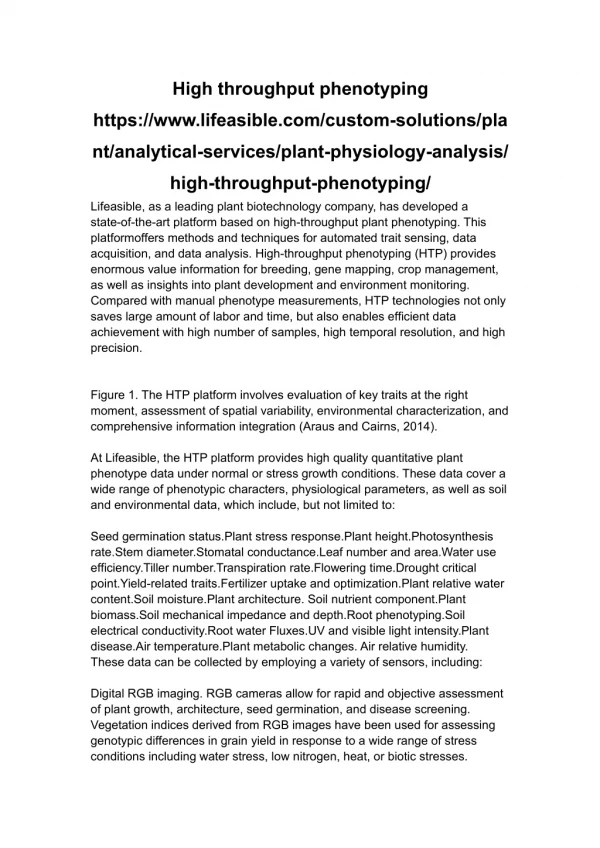
Explore the design of a high-throughput distributed shared-buffer NoC router for efficient VLSI systems. Understand the need for network-on-chip (NoC) routers in delivering high throughput for multi-core applications. Compare Input Buffered Routers (IBR) with Output Buffered Routers (OBR) and evaluate their performance using various synthetic traffic traces. Discover the benefits and limitations of output buffering and the challenges in implementing it in NoCs. Learn about the innovative approach of Distributed Shared Buffer Router design for enhanced performance.

E N D
Design of a High-Throughput Distributed Shared-Buffer NoC Router Rohit Sunkam Ramanujam*, Vassos Soteriou†, Bill Lin*, Li-Shiuan Peh‡ *Dept. of Electrical Engineering, UCSD, USA †Dept. of Electrical Engineering, CUT, Cyprus ‡Dept. of Electrical Eng. and Computer Science, MIT, USA Navneet Iyengar Dept. of Electrical Engineering, UCSD, USA Navneet Iyengar 4/30/13 ECE 284
The need for a Network on Chip (NoC) Compute Unit Router • NoC architectures are fast becoming de-facto • Efficient use of wires • A new way to organize and build VLSI systems Navneet Iyengar 4/30/13 ECE 284
The Problem – Delivering high throughput in NoCs • Why Care? • NoCs in CMPs connect general-purpose processors. • High throughput allows NoC to satisfy the comminication needs of multi-core and many core applications. • Can expect high traffic volume for current and future applications running on many-core processors. • E.g. Cache coherence between large number of distributed shared L2 caches. • It is also critical from a delay perspective when the applications have heavy communication workloads which leads to increase in queing delays of packets Navneet Iyengar 4/30/13 ECE 284
An important design choice that affects throughput • Router microarchitecture • A router’s role is to multiplex the packets onto its output links • Buffering is used to house arriving flits which cannot be immediately forwarded to the network links. • What are the types of buffering and their pros/cons? Navneet Iyengar 4/30/13 ECE 284
INPUT BUFFERED ROUTER (IBR) Input Buffered Routers (IBRs) – Flits buffered at the input ports Navneet Iyengar 4/30/13 ECE 284
IBR Pipeline RC ST LT VA SA Input 1 Output 1 Output 2 Input 2 Crossbar Switch Arbitration Acquire access to the output port through the crossbar. Switch Traversal Traverse the crossbar to reach the output link. Link Traversal Traverse the link to reach the input buffer of the next hop router. Virtual Channel Allocation Reserve an output Virtual Channel (buffering) at the next hop router. Route Computation Determine the output port of the flit based on the destination coordinates. Navneet Iyengar 4/30/13 ECE 284
IBR Limitations cycle = 1 cycle = 2 cycle = 3 Output 1 Input 1 Output 2 Input 2 Crossbar Maximal Matching: Input 2 → Output 1 Maximal Matching: Input 1 → Output 1 Output 2 is unutilized in cycle 3 although there is a flit destined for output 2. Bottleneck: Maximal matching used for arbitration is not good enough. (70-80% efficiency) Navneet Iyengar 4/30/13 ECE 284
Output queueing to the rescue … Output buffered router (OBR)– Flits buffered at the output ports First-come-first serve No switch arbitration Incoming flits directly written into the output buffers through concentrator No maximal matching Navneet Iyengar 4/30/13 ECE 284
OBR Performance cycle = 3 cycle = 1 cycle = 2 Output 1 Input 1 Output 2 Input 2 Crossbar Output links are always utilized when there are flits available. Better multiplexing of flits onto output links ⇒ higher throughput. Navneet Iyengar 4/30/13 ECE 284
Evaluation Metrics • Cycle accurate flit level simulator. • Mesh topology – Each router has 5 ports, NSEW + Injection/Ejection. • Dimension Ordered Routing (DOR) – decouple effects of routing algorithm on network performance. • 3 Synthetic traffic traces: • Uniform • Bit Complement (Complement) • Tornado • Real traffic/memory traces from running multiple threads (49 threads ⇒ 7x7 Mesh) of eight SPLASH-2 benchmarks: • Complex 1D FFT, LU decomposition, Water-nsquared, Water-spatial, Ray tracer, Barnes-Hut, Integer Radix sort, Ocean simulation. Navneet Iyengar 4/30/13 ECE 284
How much difference does it make? Uniform Traffic A throughput gap of 18%! Navneet Iyengar 4/30/13 ECE 284
How much difference does it make? Complement Traffic A throughput gap of 12%! Navneet Iyengar 4/30/13 ECE 284
How much difference does it make? Tornado Traffic A throughput gap of 22%! Navneet Iyengar 4/30/13 ECE 284
TORNADO TRAFFIC PATTERN Navneet Iyengar 4/30/13 ECE 284
Output Buffering is great … • OBRs offer much higher throughput than IBRs. • OBRs have predictable delay. • Queuing delay modeled using M/D/1 queues • Packet delays not predictable for IBRs. Navneet Iyengar 4/30/13 ECE 284
So why aren’t OBRs used in NoCs ? Input 1 Output 1 Input 2 . . . . . . Input P-1 Output P-1 Crossbar • Implementing Output Buffering requires either: • Crossbar speedup of P, where P is the number of ports. Not practical for aggressively clocked designs. • Output buffers with P write ports and a PxP2 crossbar. Has huge area and power penalties. Navneet Iyengar 4/30/13 ECE 284
Our approach: The Distributed Shared Buffer Router Current time = 2 Current time = 1 Current time = 4 Current time = 3 Current time = 6 Current time = 5 Step2: Find a conflict-free middle memory. Step1: Timestamp the flits Assign a future time at which a flit would depart the router assuming output buffering. Step4: When current time == timestamp, Read flit from middle memory to output port. Step3: Move flits from input buffers to middle memories. 4 Output 1 Input 1 5 Input 2 Output 2 6 Input 3 Output 3 Crossbar 1 Middle Memories Crossbar 2 Navneet Iyengar 4/30/13 ECE 284
Possible Conflicts Arrival Conflicts – With P input ports, a flit can have an arrival conflict with P-1 other flits. Departure Conflicts – With P output ports, a flit can have a departure conflict with P-1 other flits. By Pigeon hole principle, 2P-1 middle memories needed to avoid all arrival and departure conflicts. Navneet Iyengar 4/30/13 ECE 284
The Distributed Shared-Buffer (DSB)Router Microarchitecture Navneet Iyengar 4/30/13 ECE 284
DSB Goals • Aims at emulating the packet servicing scheme of an OBR with limited buffers and no speedup. • First-Come-First-Served servicing of flits. Objectives: • Close the performance gap between OBRs with infinite buffers and IBRs (high throughput). • Make a feasible design →low power and area overhead. • Make packet delays more predictable for delay sensitive NoC applications. Navneet Iyengar 4/30/13 ECE 284
What’s new in the DSB Router? Innovations : • Router pipeline with new stages for: • Timestamping flits • Finding a conflict free middle memory • Complexity and delay-balanced pipeline stages for a high-clocked, high-performance implementation. • Priority based flit-levelflow control to prevent packet dropping when resources are unavailable. • Evaluate power-performance tradeoff of DSB architectures with fewer than 2P-1 middle memories. Navneet Iyengar 4/30/13 ECE 284
Distributed Shared-Buffer Router pipeline If CR or VA fails CR RC XB1 + MM_WR MM_RD + XB2 LT VA TS Input 1 Output 1 Input 2 Output 2 Crossbar 1 Middle Memory Crossbar 2 Conflict Resolution + Virtual Channel Allocation Conflict Resolution: Find a conflict free middle memory. Virtual Channel Allocation: Reserve a virtual channel at the input of the next hop router. Middle Memory Read + Crossbar 2 When the current time equals the timestamp, the flit is read from the middle memory and traverses the second crossbar. Timestamp Allocation Assign a timestamp to a flit for the output port requested. Timestamp is the future time (cycle) at which the flit can depart the middle memory buffer. Crossbar 1 + Middle Memory Write Flit traverses the first crossbar and gets written into the assigned middle memory. Route Computation Determine the output port of the flit based on the destination coordinates. Link Traversal Flit traverses the output link to reach the input buffer of the next-hop router. Navneet Iyengar 4/30/13 ECE 284
Evaluation Metrics (same as for IBR vs OBR) • Cycle accurate flit level simulator. • Mesh topology – Each router has 5 ports, NSEW + Injection/Ejection. • Dimension Ordered Routing (DOR) – decouple effects of routing algorithm on network performance. • 3 Synthetic traffic traces: • Uniform • Bit Complement (Complement) • Tornado • Real traffic/memory traces from running multiple threads (49 threads ⇒ 7x7 Mesh) of eight SPLASH-2 benchmarks: • Complex 1D FFT, LU decomposition, Water-nsquared, Water-spatial, Ray tracer, Barnes-Hut, Integer Radix sort, Ocean simulation. Navneet Iyengar 4/30/13 ECE 284
Performance on Uniform traffic A throughput gap of just 9% Navneet Iyengar 4/30/13 ECE 284
Performance on Complement traffic A throughput gap of just 4% Navneet Iyengar 4/30/13 ECE 284
Performance on Tornado traffic A throughput gap of just 8% Navneet Iyengar 4/30/13 ECE 284
Performance of DSB on SPLASH-2 benchmarks Small difference in packet latency between OBR and DSB routers is mainly due to the limited buffering in the DSB router. Raytrace, Barnes and Ocean traces have very little contention. For these traces, IBR has lower latency because of a shorter pipeline. Performance of DSB is very close to an OBR with same number of pipeline stages. Huge performance improvements over IBR in traces exhibiting high contention and demanding high bandwidth. 64% 72% 97% Navneet Iyengar 4/30/13 ECE 284
Higher throughput – At what cost? CR RC XB1 + MM_WR MM_RD + XB2 LT VA TS Input 1 Output 1 Input 2 Output 2 Crossbar 1 Middle Memory Crossbar 2 Two crossbars instead of one: With N middle memories, need one PxN and one PxN crossbar. Middle memory buffers – Can have fewer input buffers to compensate for extra middle memory buffers. TS stage instead of Switch Arbitration in IBRs Extra stage for Conflict Resolution Extra power !! Navneet Iyengar 4/30/13 ECE 284
Power-Performance tradeoff Theoretically, 2P-1 middle memories needed to resolve all conflicts. For a 5-port mesh router, need > 9 middle memories, a 5x9 and a 9x5 crossbar – large power overhead. What is the impact of using fewer than 2P-1 middle memories? Navneet Iyengar 4/30/13 ECE 284
Power and Area Comparison Router power overhead of 50% for DSB-5 router If NoC consumes 10% of tile power, tile power overhead of only 3.5% for DSB-5 router If NoC consumes 20% of tile power, tile power overhead of only 7% for DSB-5 router Navneet Iyengar 4/30/13 ECE 284
Thank you Questions? Navneet Iyengar 4/30/13 ECE 284