Download
1 / 25
260 likes | 480 Views
Heterogeneous NoC Router. Moti Mor Tomer Gal Instructor: Yaniv Ben Itzhak. Mid Presentation. 03.03.2013. Project Goals. Research about different Heterogeneous NoC Architectures Design an architecture of a heterogeneous router Architecture Implementation

E N D
Heterogeneous NoC Router Moti Mor Tomer Gal Instructor: Yaniv Ben Itzhak Mid Presentation 03.03.2013
Project Goals • Research about different Heterogeneous NoC Architectures • Design an architecture of a heterogeneous router • Architecture Implementation • Basic Measurements of speed and performance: • Latency • Throughput • Power • Area • Maximum Frequency M
Introduction • Network-on-Chip (NoC) is a new approach to design the communication subsystem of SoC and Chip-Multi-Processors (CMP). • Clients communicates through a network of routers • Overcoming BUS bottlenecks, Performance improvement. R R R C C C R R R C C C R R R C C C T
Background • The SoC units communicate through a network of routers • Each router is assigned for a single unit • Supports many simultaneously connections • Credit-based flit-level flow control T
Background – XY mesh NoC C = Client R R R Less Bottlenecks R C C C = Router R R R C C C R R R C C C T
Architectures Review • Considered architectures: • Input Buffer • Shared Memory • Shared Buffer M
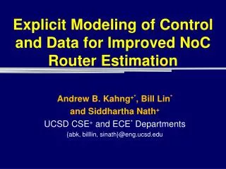
Architectures Review-Cont. • Input Buffer • Flits are stored in the input buffers and then traversed through the cross-bar to the output ports. M
Architectures Review-Cont. • To acquire heterogeneity of the Input Buffer: • Variable number of arbiters are needed for each output port • Input buffers need different write and read rates • In order to avoid saturation, the minimum buffer read rate must be at least ILW (Ingress link width) • In order to allow burst handling , the read rate must at least be ELW (Egress link width) of the largest out-port • Limited Decoupling between in-ports & out-ports M
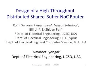
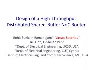
Architectures Review-Cont. • Shared Memory • In-ports store incoming flits, out-ports read flits from the shared memory • Total flit read (write) rate is determined by the total out-port (in-port) bandwidth, Resulting in better rate matching between in-ports and out-ports M
Architectures Review-Cont. • Shared Memory • High latency – Implemented by linked lists which requires 5 memory access cycles for each R/W. • High hardware overhead- Due to long cycle time for R/W from the shared memory , there are two possible solutions: • Collecting several flits and writing them together to the shared memory – requires adding additional buffers. • Shared memory based on multi-port queues – increases size quadratically with the number of ports M
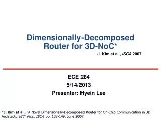
Architectures Review-Cont. • Shared Buffer – Chosen Architecture • In-ports store incoming flits to the shared buffer, out-ports read flits from the shared buffer • Each incoming flit is assigned with a Time Stamp (TS) and Shared Buffer Allocation T
Architectures Review-Cont. • Shared Buffer – Chosen Architecture • Eliminates the need of linked lists management • Decoupling in-ports and out-ports (A flit can acquire any shared buffer, and each shared buffer can be connected to any out-port) • Buffers are shared among all the ports, thus, a better buffer utilization is achieved T
Shared Buffer - Architecture Details • Stage 1 - Buffer Write: • Incoming flits are written into the input-buffers. • The input buffers are segmented according to the number of VCs of each input port T
Shared Buffer - Architecture Details • Stage 2 – Routing Calculations: • This stage is relevant only for the head flit • Output port is being determined according to the flit’s coordinates T
Shared Buffer - Architecture Details • Stage 3.1 – VC Allocation: • This stage is relevant only for the head flit • Arbitration for free virtual channels at the input of the next-hop router • Managing a free VCs list for each output port T
Shared Buffer - Architecture Details • Stage 3.2 – Time Stamping (TS): • Assigning ingress flits into the shared buffer by resolving the departure conflict • Assigns time slots in a cyclical fashion • Assigns the earliest departure time for as many flits as possible T
Shared Buffer - Architecture Details • Stage 4 – Shared Buffer Allocation: • Flits that were assigned to time slots in the TS stage are assigned to a specific shared buffer • Responsible to maintain the order of flits from the same packet • Should consider the write constraints of the shared buffers (Can cause Arrival Conflict) • If not succeeded Re-enters the TS stage T
Shared Buffer - Architecture Details • Departure Conflict - • Occurs for out-port O when more than ELWO flits are assigned with the same time stamp. • Arrival Conflict – • Occurs when trying to write more flits than allowed to a certain shared buffer M
Shared Buffer - Architecture Details • Stage 5 – Crossbar 1 (XB1) & SB Write: • Flits are traversed trough the first XB and written in the Share Buffers. M
Shared Buffer - Architecture Details • Stage 6 – SB Read & Crossbar 2 (XB2) : • Flits stored in time-slot 0 are read from the shared buffer and traversed trough the second XB. • Each time-slot i advance to time-slot i-1. M
Shared Buffer - Architecture Details • Stage 7 – Link Traversal: • The flits are transmitted to the downstream router M
Shared Buffer - Architecture Details • Speed-up: • Defined as the number of flits that can be written to a certain shared buffer (write to different time slots) • Allows reducing the number of shared buffers and maintain conflict-free router • Reducing the number of shared buffers decreases the area and power consumption, despite the increase in the number of MUXs, and the size of the XB1. M
Shared Buffer – Advantages • Best decoupling between ingress & egress • Better buffer utilization (shared among all ports) Vs the input buffer • Less overhead than the shared memory due to linked lists handling • Can tolerate defective shared buffers T
Shared Buffer Heterogeneity • Modular Parameters: • Number of Virtual Channels per port • In-port & Out-port width • Number of shared buffers • Shared buffer length/size • Speed-up T
Project Status • Research about different Heterogeneous NoC Architectures • Design an architecture of a heterogeneous router • Architecture Implementation • Basic Measurements T