Download
1 / 13
130 likes | 231 Views
Modeling of Inert Gas Distribution in Commercial Transport Fuel Tanks. William M Cavage Project Manager - Fuel Tank Inerting FAA AAR-440, Fire Safety R&D Branch. June 13th-14th, 2002 International Systems Fire Protection Working Group CAA House - London, UK. Outline. Background

E N D
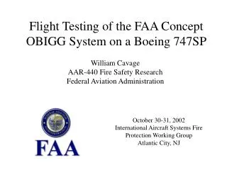
Modeling of Inert Gas Distribution in Commercial Transport Fuel Tanks William M CavageProject Manager - Fuel Tank Inerting FAA AAR-440, Fire Safety R&D Branch June 13th-14th, 2002International Systems Fire ProtectionWorking Group CAA House - London, UK
Outline • Background • Preliminary Model Methods • Scale Tank Testing • Engineering Model • Summary AAR-422 Fire Safety R&D
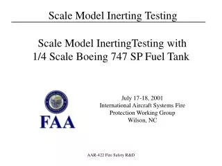
Background • FAA Would Like to Develop Cost Effective Methods of Modeling Inert Gas Distribution in Commercial Transport Fuel Tanks • Developed a Scale Tank Model of the 747SP CWT • Made From Plywood Using NTSP Shepard Report Drawings • Variable NEA Deposit Capabilities, Oxygen Analyzer in Each Bay • Preliminary Results Didn’t Model Gas Distribution Well • Developed Multiple Bay Inert Gas Distribution Engineering Model of 747SP CWT • Models 6 Bay Tank in Test Article Venting Config. (half blocked) • Based on Ullage Washing Model AAR-422 Fire Safety R&D
Inert Gas Distribution Modeling • Preliminary Models • Original Simple Inerting Model Developed by Ivor Thomas (FAA CSTA for Fuel Systems) • Tracks the Volume of Oxygen In and Out of a Tank and Calculates Oxygen Concentration Given the Tank Volume • Uses a Basic Spreadsheet Layout and Runs Instantaneously Given the Volume of the Tank, The Flow Rate and Purity of the NEA • Basic Formula for Model • Model Results Compared Well with Ullage Washing Data AAR-422 Fire Safety R&D
Simple Inerting Model Results Compared with Ullage Washing Data AAR-422 Fire Safety R&D
Scale CWT Tests • Original Plywood Model Results Encouraging, But NEA Distribution Did Not Compare Well with Full-Scale Data • Made Several Improvements to Scale Tank • Better Modeling of Vent System Cross Sectional Flow Areas • Ensured Lid Did Not Leak Around Bay Tops which Would Alter Flow Pattern • Performed Additional Testing • Scale Tank Inert Gas Distribution Results Compared Very Well to Data Acquired on 747SP Full-Scale Test Article • Additional Testing Planned for Different Deposit Methods (Onboard System) AAR-422 Fire Safety R&D
Scale Plywood CWT Model AAR-422 Fire Safety R&D
Scale Plywood CWT Model Data Comparison AAR-422 Fire Safety R&D
Multiple-Bay Inerting Engineering Model • Model Calculates Inert Gas Distribution in 6 Bay Tank, in terms of Oxygen Concentration Evolution, Given NEA Purity and Bay Deposit Flow Rates • Based on Original Inerting Model by Ivor Thomas which Tracks Oxygen In and Out of Each Bay Assuming Perfect Mixing During the Time Step • Assumes an “Outward” Flow Pattern and Splits Flow into a Bay to Adjacent Bays Using Out Flow Area Relationships • Presently Does Half Blocked Venting Case Only • Compared with Full-Scale Test Article • Must Run ACMs to Obtain Data that Agrees with Engineering Model (Which Assumes Perfect Mixing) • Agrees Best for Single Deposit Case Compared with Scale Tank Data AAR-422 Fire Safety R&D
Engineering Model Assumed Flow Pattern Bay 1 Flow Out Bay 2 Flow In Bay 3 Bay 4 Bay 5 Bay 6 Flow Out AAR-422 Fire Safety R&D
Engineering Model Data Comparison AAR-422 Fire Safety R&D
Full-Scale Data Compared with Modeling Methods AAR-422 Fire Safety R&D
Summary • Scale Tank Testing Produced Good Results when Compared with the “Good Mixing” Full-Scale Testing • Cost Effective Modeling Method • Simple Engineering Modeling Methods Can Produce Fair Results in a Very Cost Effective Way • Additional Work Needed to Improve Model for Multiple Deposits • Both Methods Predict VTE Required (Amount of NEA) Very Well, Given a Highly Localized Deposit AAR-422 Fire Safety R&D