Download
1 / 7
70 likes | 197 Views
Detailed summary of critical dimensions and layering elements for stave design in ANSYS software, with focus on dimensioning datums and theoretical measurements. Commentary on carbon fiber modeling with ANSYS software.

E N D
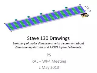
Stave 130 DrawingsSummary of major dimensions, with a comment about dimensioning datums and ANSYS layered elements. PS RAL – WP4 Meeting 2 May 2013
Stave Dimensions Critical Dimensions: • Overall Length 1277 • Width 120 (likely to change, hopefully narrower, due to modifications with hybrid) • SMC area 100 x 50 • EOS at Z=0 to Silicon Edge 0.1mm • Start of Silicon from Z=1277.1 = 3.36 • Module to Module Gap 0.46mm • Pitch of Modules 98mm
Stave thicknesses • Wirebond to Wirebond 7.88 • ASIC to ASIC 6.18
Stereo Side • Pitch of Modules 98mm • EOS at Z=0 to Silicon Edge 0.102mm • Module to Module Gap 0.3817 All dimensions theoretical to show difference!
Dimensioning Datums NOTE: The tape is not to be used as a datum. The tape will be positioned to a nominal accuracy in order for the wire bond pad to be ‘within tolerance’ Laser drilled hole in Z=0 locator foil.
Thoughts about ANSYS carbon fibre modelling • ANSYS 14 has stopped ‘supporting’ certain elements. • There are 2 elements which can be used for layered analysis • SHELL181 • SOLID185 • ANSYS has a ‘Section’ menu, one of which is Shell, where you can construct a layup. This menu seems to work for solid as well as shell elements. • It seems the layup can only be associated with 1 coordinate system.