Download
1 / 87
990 likes | 1.37k Views
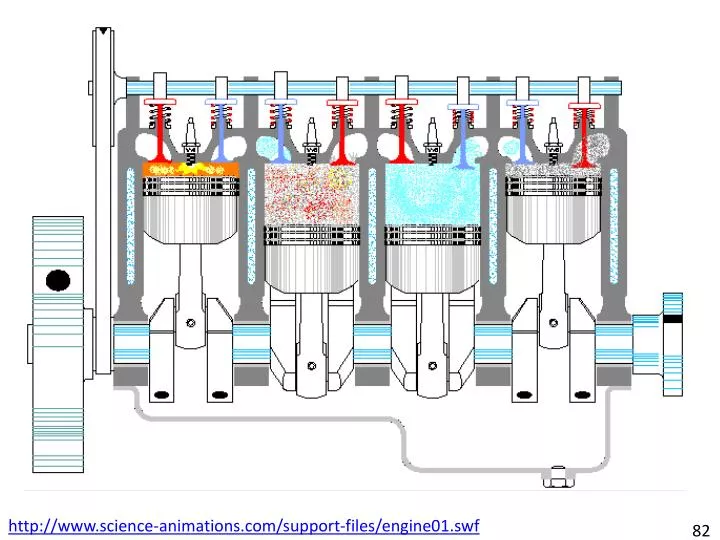
http://www.science-animations.com/support-files/engine01.swf. 82. THERMODYNAMICS-II. I.C. ENGINE TESTING. By:- Harjinder Pal Singh Lect. Mech. Dated:20-09-2012 Govt. Polytechnic College Batala. 81. I.C. ENGINE TESTING. INTRODUCTION:

E N D
http://www.science-animations.com/support-files/engine01.swf 82
THERMODYNAMICS-II I.C. ENGINE TESTING By:- Harjinder Pal Singh Lect. Mech. Dated:20-09-2012 Govt. Polytechnic College Batala 81
I.C. ENGINE TESTING INTRODUCTION: The basic task in the design and development of engines is to reduce the cost and improve the efficiency and power output. In order to achieve the above task, the ‘development engineer’ has to compare the engine developed with other- 80
I.C. ENGINE TESTING INTRODUCTION: -engines in terms of its output and efficiency. Towards this end he has to test the engine and make measurements of relevant parameters that reflect the performance of the engine. I.C. engine generally operates within a useful- 79
I.C. ENGINE TESTING INTRODUCTION: -range of speed. Some engines are made to run at fixed speed by means of speed governor, which is its rated speed. The performance of the engine depends on the inter-relationship between the power developed, speed and the specific fuel - 78
I.C. ENGINE TESTING INTRODUCTION: -consumption at each operating condition within the useful range of speed and load. 77
I.C. ENGINE TESTING The following factors are to be considered in evaluating the performance of an engine: Maximum power or torque available at each speed within the useful range of speed. The range of power output at constant speed for stable operation of the engine. The different speeds should be related at equal intervals within the useful speed range. 76
I.C. ENGINE TESTING (iii) Brake specific fuel consumption at each operating condition within the useful range of operation. (iv) Reliability and durability of the engine for the given range of operation. 75
I.C. ENGINE TESTING Purpose of Testing an I.C. Engine: In general the purpose or significance of testing an I.C. engine is to determine the following: To determine rated power output with respect to the fuel consumption in Kg per Kw-hr of brake power output. 74
I.C. ENGINE TESTING Purpose of Testing an I.C. Engine: (ii) To determine the mechanical and thermal efficiencies of the engine. (iii) To see the performance of the engine when loaded at different loads. 73
I.C. ENGINE TESTING Purpose of Testing an I.C. Engine: (iv) To determine the quantity of lubricating oil required per bp Kw hr. (v) To determine the quantity of cooling water required per bp Kw hr. (vi) To determine the overload carrying capacity of the engine. (vii) To prepare the heat balance sheet of the engine. 72
I.C. ENGINE TESTING Some Important Terms as per ISI Standard: Speed : The speed of an engine is the mean speed of its crank shaft in revolutions per minute (RPM), except in case of ‘free piston’ engines where the speed is the number of cycles per minute , of the reciprocating components. Steady Load Speed Band: It is the maximum total variation in speed expressed as a %age of the mean speed, which may occur while there is no change in external load conditions. 71
I.C. ENGINE TESTING Some Important Terms as per ISI Standard: 3. Continuous Power: The power which the engine is capable of delivering continuously between the normal maintenance intervals stated by the manufacturer, at stated speed and under stated operating conditions. 4. Indicated Power: It is the total power developed in the working cylinder by the gases on the combustion side of the working pistons. 5. Friction Power: It is the power consumed in frictional resistance. 70
I.C. ENGINE TESTING Some Important Terms as per ISI Standard: 6. Brake Power: It is the total power measured at the driving shaft. 7. Fuel Consumption: The quality of fuel consumed by the engine per unit time of the stated power and under stated operating conditions. 8. Specific Fuel Consumption: It is the quantity of fuel consumed per unit of power per unit of time. It is generally expressed in gms of fuel consumed per kW hr or B.H.P./bp. 69
I.C. ENGINE TESTING Some Important Terms as per ISI Standard: 9. Standard Operating Conditions : The following are the standard operating conditions: Mean Barometric Pressure: It is taken as 736 mm of mercury (Hg). Intake Air Temperature : It is taken as 3000k or 270C 68
I.C. ENGINE TESTING Engine Power : The energy flow through the engine is expressed in three distinct terms. They are ‘indicated power’, ip, ‘friction power’, fp and ‘ brake power’, bp. ‘Indicated power’ can be computed from the measurement of forces in the cylinder and ‘break power’ from the measurement of forces at the crank shaft of the engine. The ‘friction power’ can be estimated by motoring the engine or from the difference between ip and bp. i.e. fp=ip-bp 67
I.C. ENGINE TESTING Indicated Mean Effective Pressure (Pim): It may be defined as, the constant pressure acting over the full length of the stroke and capable of producing the same amount of work, as is actually produced during the complete cycle of the engine. It is generally denoted by ‘Pim’ or i.m.e.p. As, the pressure in the cylinder varies throughout the cycles and the variation can be expressed with respect to the volume or crank angle rotation to obtain p-V or p-θ diagrams, 66
I.C. ENGINE TESTING Indicated Mean Effective Pressure (Pim): respectively. However, such a continuous variation does not readily lend itself to simple mathematical analysis in the computation of ip. If an average pressure for one cycle can be used, then the computations become far less difficult. Refering figure, as the piston moves back and forth between TDC and BDC, the process lines on the p-V diagram indicated the successive states of the working fluid through the cycle. 65
I.C. ENGINE TESTING Indicated Mean Effective Pressure (Pim): The indicated network of the cycle is represented by the area 1-2-3-4 enclosed by the process lines for that cycle. If the area of rectangle A-B-C-D equals, the area 1-2-3-4, the vertical distance between the horizontal lines AB and CD respectively gives the ‘indicated mean effective pressure’, imep. It is a mean value expressed in N/m2, which when multiplied by the displacement volume or swept volume, Vs gives the ‘same indicated net work’ as is actually 64
I.C. ENGINE TESTING Indicated Mean Effective Pressure (Pim): p-V diagram for an ideal four-stroke cycle engine
I.C. ENGINE TESTING Indicated Mean Effective Pressure (Pim): produced with the varying pressures. PimX(V1-V2) = Net work of cycle Pim= Also, Pim= = If, a= area of indicator diagram in cm2. l= length of the indicator diagram in cm 63
I.C. ENGINE TESTING Indicated Mean Effective Pressure (Pim): And s = spring no. or spring strength in N/m2 per cm. Then Pim = N/m2 The value of the area measured, when divided by the piston displacement and multiplied by the spring number of the indicator, results in the mean ordinate or indicated mean effective pressure , Pim. 62
I.C. ENGINE TESTING Brake Mean Effective Pressure (Pbm): It may be defined as the mean effective pressure acting on the face of piston, which would develop brake power equivalent to that during actual varying pressure condition. It is generally denoted by Pbm or b.m.e.p. 61
I.C. ENGINE TESTING Brake Mean Effective Pressure (Pbm): Friction mean effective pressure (Pfm) is that portion of mean effective pressure (Pim), which is required to overcome friction losses and brake mean effective pressure is the portion, which produces the useful power delivered by the engine. 60
I.C. ENGINE TESTING Brake Mean Effective Pressure (Pbm): Pim=Pfm+ Pbm Also, Break Power, bp= kW Where Pbm = Break mean effective pressure in N/m2. L= Length of stroke in m. A = Area of piston in m2. N= number of working strokes/min K= number of cylinders of the engine. Mechanical Efficiency, ηm== 59
I.C. ENGINE TESTING Piston Speed : It is the average or mean distance travelled by the piston of the engine in one minute. i.e., Piston speed = 2 L.N. m/min Where, L = Length of stroke (m) And N= Revolutions per minute of the crank shaft. 58
I.C. ENGINE TESTING Fuel-Air (F/A) or Air-Fuel (A/F) Ratio: The relative proportions of the fuel and air in the engine are very important from the stand point of combustion and efficiency of the engine. This is expressed either as a ratio of the mass of the fuel to that of the air or vice versa. In the SI engine the fuel-air ratio practically remains constant over a wide range of operation. In CI engines at a given speed the air flow does not vary with load, it is the fuel flow that varies directly with load. Therefore, the term fuel-air - 57
I.C. ENGINE TESTING Fuel-Air (F/A) or Air-Fuel (A/F) Ratio: -ratio is generally used instead of air-fuel ratio. A mixture that contains just enough air for complete combustion of all the fuel in the mixture is called a ‘chemically correct’ or ‘stoichiometric fuel-air ratio’. A mixture having more fuel than that in a chemically correct mixture is termed as ‘rich mixture’ and a mixture that contains less fuel or excess air is called a ‘lean mixture’ or ‘weak mixture’. The ratio of actual fuel-air ratio to the chemically correct - 56
I.C. ENGINE TESTING Fuel-Air (F/A) or Air-Fuel (A/F) Ratio: -fuel-air ratio is called ‘equivalence ratio’ and is denoted by ɸ, ɸ = Accordingly, ɸ= 1 means chemically correct mixture. ɸ< 1 means lean mixture or weak mixture. And ɸ> 1 means rich mixture. 55
I.C. ENGINE TESTING Calorific Value (CV) : ‘Calorific value’ of a fuel is the thermal energy released per unit quantity of the fuel when the fuel is burned completely and the products of combustion are cooled back to the initial temperature of the combustion mixture. Other terms used for the calorific value are ‘heating value’ and ‘heat combustion’. When the products of combustion are cooled to 250C practically, all the water vapour resulting from the combustion process is - 54
I.C. ENGINE TESTING Calorific Value (CV) : -condensed. The heating value so obtained is called the ‘higher calorific value’ or ‘gross calorific value’ of the fuel. The ‘lower or net calorific value’ is the heat released when vapour in the products of combustion is not condensed and remains in the vapour form. 53
I.C. ENGINE TESTING Measurement of Air Supply of an I.C. Engine: To measure air supply, the orifice method can be used if pressure pulsations could be damped out by some means. The usual method of damping out the pressure-pulsations is to fit an air box of suitable volume (500 to 600 times the swept volume in single cylinder engines and less in case of multi-cylinder engines) to the engine with an orifice placed in the side of the box, remote from the engine as shown in figure. 52
I.C. ENGINE TESTING Measurement of Air Supply of an I.C. Engine: Measurement of Air by Air Box Method. 51
I.C. ENGINE TESTING Measurement of Air Supply of an I.C. Engine: Let a= area of orifice in m3. Cd= Coefficient of discharge of the orifice. ΔH= Difference of pressure as measured in cm. of water. Ma= Mass of one cubic metre of air, in kg. Mw=Mass of one cubic metre of water, in kg. H= Head causing flow through the orifice in m. of air. 50
I.C. ENGINE TESTING Measurement of Air Supply of an I.C. Engine: V= Velocity of air flowing through the orifice in metre per sec. Q= Discharge of air flowing through the orifice , in m3 per sec. Now, consider one m3 of air at a pressure of ‘p’ N/m2 and absolute temperature ‘T’, Kelvin. Then, applying gas=n pv=Ma.RT But v=1m3 Ma= 49
I.C. ENGINE TESTING Measurement of Air Supply of an I.C. Engine: Ma= ( R=287 J/kg-K) ----1 Now, H = X m of air Also, V = Cd. And Q= a.V Q=a.Cd. -----2 Now, using the equation 1 and 2 the mass of the air supplied can be calculated as follows. Mass of air supplied = Q.Ma 48
I.C. ENGINE TESTING Air-Standard Efficiency: The air-standard efficiency is also known as ‘thermodynamic efficiency’. It is mainly a function of compression ratio and other parameters. It gives the upper limit of the efficiency obtained from an engine. For engines working on Otto cycle, the air standard efficiency , Where, r= Compression ratio And 47
I.C. ENGINE TESTING Mechanical Efficiency (: It may be defined as the ratio of the power obtained at the crank shaft, i.e. brake power(bp) to the indicated power (ip). Thus, Mechanical Efficiency () = Mechanical efficiency takes into account the mechanical losses in an engine. Mechanical losses of an engine may be further subdivided into the following groups. (i) Friction losses as in case of pistons, bearings, 46
I.C. ENGINE TESTING Mechanical Efficiency (: gears, valve mechanisms. With the development in the bearing design and materials , improvement in gears etc. , these losses are usually limited from 7 to 9 percent of the indicated power output. (ii) Power is absorbed by engine auxilliaries such as fuel pump, lubricating oil pump, water circulating pump, radiator magneto and distributor, electric generator for battery charging, radiator fan etc. These losses may - 45
I.C. ENGINE TESTING Mechanical Efficiency (: -account for 3 to 8 percent of the indicated output. (iii) Ventilating or faning action of the flywheel. This loss is usually below 4 percent of the indicated output. (iv) Work of charging the cylinder with fresh charge and discharging the exhaust gases during the exhaust stroke. In case of two-stroke engines the power absorbed by the scavenging pump etc. These losses may account for 2 to 6 percent - 44
I.C. ENGINE TESTING Mechanical Efficiency (: -of the indicated power output. In general, the mechanical efficiency of engines varies from 65 to 85%. 43
I.C. ENGINE TESTING Indicated Thermal Efficiency (: It may be defined as the ratio of heat converted into indicated work to the heat energy supplied by the fuel, during a specified period of time. So, Indicated thermal efficiency , (ith)= = Where, Mf = Mass of fuel supplied to the engine per minute. CV = Lower calorific value of the fuel. 42
I.C. ENGINE TESTING Brake Thermal Efficiency (: It may be defined as the ratio of heat equivalent to brake power (bp) to the heat energy supplied by the fuel during a specific period of time. So, Brake thermal efficiency , (bth)= = Where, Mf = Mass of fuel supplied to the engine per minute. CV = Lower calorific value of the fuel. 41
I.C. ENGINE TESTING Brake Thermal Efficiency (: In modern engines, an indicated thermal efficiency of almost 28 percent is obtainable with gas and gasoline spark-ignition engines having a moderate compression ratio and as high 36 percent or even more with high compression ratio diesel engines, i.e. CI Engine. 40
I.C. ENGINE TESTING Relative Efficiency (: The ‘relative efficiency’ or ‘efficiency ratio’, as it is sometimes called, is the ratio of the actual efficiency obtained from an engine to the theoretical efficiency of the engine cycle. So, Relative Efficiency ()= Relative efficiency for most of the engines varies from 85 to 95 % with theoretical air and decreases rapidly with insufficient air to about 75% to 90 % of air. 39
I.C. ENGINE TESTING Volumetric Efficiency (: The ‘Volumetric efficiency’ is measure of the success with which the air supply and thus the charge, is induced into the engine cylinder. It is very important parameter, since it indicates the breathing capacity of the engine. ‘Volumetric efficiency’ is defined as the ratio of volume of air induced at ambient condition to the swept volume or it may also be defined as the ratio of actual mass of air drawn into the engine cylinder during a given period of time to - 38
I.C. ENGINE TESTING Volumetric Efficiency (: -the theoretical mass which should have been drawn in during that same period of time, based upon the total piston displacement of the engine and the temperature as well as pressure of the surrounding atmosphere. So, Here, mth= Where is the density of air. Vs is the swept volume. n is the number of intake strokes per min. 37
I.C. ENGINE TESTING Volumetric Efficiency (: For a four-stroke engine n=N/2 and for a two-stroke engine n=N, where N is the speed of the engine in rev/min. The actual mass is a measured quantity. The theoretical mass is computed from the geometry of the cylinder, the number of cylinders and the speed of the engine in conjunction with the density of the surrounding atmosphere. 36
I.C. ENGINE TESTING Volumetric Efficiency (: Volumetric efficiency for a naturally aspirated engine is generally about 75%. Mathematically, Volumetric Efficiency, ()= 35
I.C. ENGINE TESTING Determination of Indicated and Brake Power: In this method, to find out ip an indicator is used to find out the mean effective pressure. This method is used for slow speed engines. An indicator is an instrument which produces a graphic record of the pressure inside the engine cylinder for every position of the piston as it reciprocates. It consists of a small cylinder fitted with a piston, the under side of which is placed in communication with the cylinder. The upper side of the indicator piston is kept in - 34