Download
1 / 25
250 likes | 389 Views
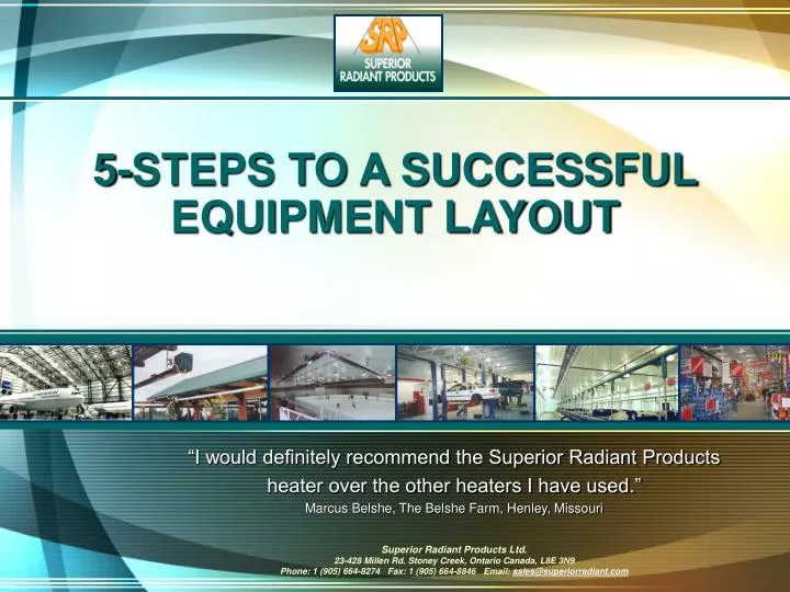
5-STEPS TO A SUCCESSFUL EQUIPMENT LAYOUT. 5-Steps to a successful equipment layout. Step 1: Review the building Step 2: Do the calculation for heat loss Step 3: Verify your conclusion Step 4: Choose your heater size Step 5: The layout. Step 1: Review the building.

E N D
5-Steps to a successful equipment layout • Step 1: Review the building • Step 2: Do the calculation for heat loss • Step 3: Verify your conclusion • Step 4: Choose your heater size • Step 5: The layout
Step 1: Review the building • What are the insulation values (R-values) of walls and ceiling? • Where are the windows and doors located? • What is the building height? • Is the roof pitched, flat or round? • Are there any cranes? Height of crane rails? Would heaters go above or below? • Are there any exhaust fans? What is the cfm? • Do any exhaust fans run all the time? Or only selected times? • Are there makeup air units? What's their capacity? • Is there storage racking? Where is it located? Will it interfere with installation or impact performance of the heater?
Heat Loss Factors • R-Value:The thermal resistance of a barrier system. The R-value is the reciprocal of the U-value. The higher the R value, the less heat is transmitted throughout the material. • U-Value:A measure of air-to-heat transmission (loss or gain) due to the thermal conductance and the difference in indoor and outdoor temperatures. As the U-value decreases, so does the amount of heat that is transferred through the material. The lower the U-value, the more restrictive the material is to heat transfer. Reciprocal of R-value. • Degree Days:A unit of measure expressed as Heating Degree Days (HDD) and/or Cooling Degree Days (CDD). Derived from the variance between the average temperature during a given time period (month, season, year) and a reference point, usually 65oF.(definition courtesy Silicon Valley Power)
Step 2: Do calculation for heat loss • Please refer to Heat Calc program for details.
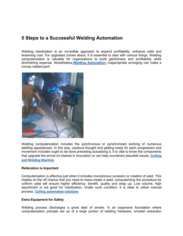
8000 7000 6000 5000 4000 DEGREE DAYS (65 DEGREE BASE) 3000 2000 1000 0 0 5 15 25 35 45 55 65 BTUs PER SQUARE FOOT Step 3: Verify your conclusion • Verify using BTUs per foot “rule of thumb”
EDMONTON COMMERCIAL BUILDING 60 to 70 BTUs per square foot TORONTO COMMERCIAL BUILDING45 to 50 BTUs per square foot ATLANTA COMMERCIAL BUILDING 20 to 30 BTUs per square foot Comparisons of degree day selections
Comparisons of degree day selections • Atlanta, Georgia • Well insulated, new construction • Commercial application • Manufacturing • BTUs per foot = 20 to 30 • Older building, poorly insulated • Commercial application • Manufacturing • BTUs per foot = 40 to 50 • Toronto, Ontario • Well insulated, new construction • Commercial application • Manufacturing • BTUs per foot = 45 to 50 • Older building, poorly insulated • Commercial application • Manufacturing • BTUs per foot = 50 to 65
Heat Load = Number of Heaters Did You Know? Heater Size Step 4: Choose the heater size • Determine the hanging height of the heater • Generally the higher the hanging height, the larger the burner you can use. For example, a 25ft ceiling could have a 220MBH heater, whereas a 16ft ceiling would only use a 100MBH. Larger may be too intense. • Cranes could affect heater choice. If you can hang them above the crane the normal rules apply; but if you have to hang them below the rails then you must adjust the height for comfort. • Consider the location of work stations and people movement through those areas. A large heater above a work station might overexpose occupants to heat. However, if people are constantly moving in and out of the work station, a larger heater may be suitable.
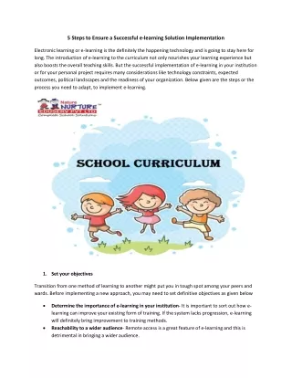
Examples of suggested mounting heights for a typical tube heater
Special Situations • Loading Docks: Loading docks should have slightly more heat than the normal load because of wind and door openings. Two-Stage Heaters work well to overcome sudden cold.
Special Situations • Exterior Applications: Outdoor patios, golf driving ranges, porticos and driveway de-icing are best done with R-Series Heaters. Heaters are generally placed closer to the ground to get more direct radiant effect.
Special Situations • Car Wash: The environment in a car wash can be very corrosive. Water absorbs infrared much more than air so more input of heat is needed. The UXR Heater is available with stainless steel options, including tube, coupler and hardware. This will stand up to a severe environment much better then a standard UXR.
Special Situations • Low Ceilings: The award-winning L-Series is designed for low ceiling applications where more even radiant output is desired. Long hallways, covered patios and animal confinement are good applications. L-Series Heater WINNER “Most Innovative HVAC Product” CIPHEX West 2002
Premier-VS Vacuum Systems • This award-winning system is suitable for many applications, especially: • Buildings with work stations where people operate in one place (i.e. packaging areas, assembly lines or airport baggage areas). • Large canvas structures where minimum vent penetration is allowed. Side wall venting is preferred with canvas roofs. This type of structure requires a lot of heat as well. • Underground garages and in-between floors where venting through the roof is impossible. • Facilities where the design / owner requires centralized controls • Facilities where the design / owner requests variable heater rates • Vacuum system safety control
Common Misconception: Very high ceilings require user to choose high intensity over low intensity. Low intensity radiant does not get to the floor. In fact, both send the same amount of energy to the floor. High intensity is concentrated so you feel it more than the tube heater which spreads it down the tube. Also you can see the high intensity working with the reddish glow where the tube heater has no glow at all. Did You Know? High Intensity Heaters • High intensity heaters naturally vent into the building space. Always remember to: • Allow for mechanical ventilation. • Take mechanical ventilators into account in your heat loss calculation. • High intensity heaters are used primarily for spot heating because: • A large degree of heat can be focused on a smaller area. • They are very effective for small work stations in large, drafty buildings or by overhead doors.
Step 5: The layout • A fundamental concept: • Low intensity heaters are hotter at the burner end (900oF – 1,000oF ) than the flue end (400oF to 500oF) • Therefore, for best comfort and where suitable: • Place heater head to tail • Use U configuration • Place the “hot end” over the “cold spots” (i.e. at doors, or near cold walls)
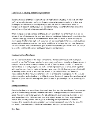
150’ – 0” 14’ x 12’ Ux 150 Ux 150 50’ 50’ 20’ – 3” 20’ – 3” Common Vented 40’ 40’ 100’ – 0” 14’ x 12’ 14’ x 12’ Ux 150 Common Vented Ux 150 Ux 150 50’ 50’ Ux 150 14’ x 12’ 20’ – 11” Perimeter Heating • When buildings have large areas relative to heat loss, a perimeter layout may be preferred. Put heat over the greatest heat loss area (i.e. exterior walls, doors, windows and loading docks). Place the heaters parallel to walls and doors, approximately the same distance away from the walls as the hanging height.
149’ – 2” 10’ x 10’ 12’ x 14’ 15’ – 1” Ux 125 30’ 20’ Ux 100 Ux 100 Common Vented 20’ 10’ 20’ Ux 125 79’ – 10” Ux 125 40’ 40’ Ux 125 Common Vented 15’ – 7” Conventional layout • Place the burners near exterior walls but preferably not closer than their hanging heights unless side shields are used. • The configuration may be: flue then burner, or flue pointing to common venting.
Side shields reflect at least 15% more infrared energy to the floor compared to tilting the shield at a 45oangle. Did You Know? 45 degree angle Side shields Use of side shields • Use of side shields are recommended: • Where heaters have to be placed closer to the wall than their hanging height or shelves allow. • Along walls where wall hanging brackets are used, such as patios. • In hockey arenas to reflect the heat back to the people, not at the ice.
Venting Options • In all cases, local codes apply for venting diameters and lengths. Ensure vent lengths described in the manual are maintained. • 30’ maximum vent length • 30’ maximum fresh air length • 50’ combined
Common Venting • Definition: When more than one heater is vented through a “common stack”, whether that stack vents through the roof or through the wall. • Sizing of the vents is governed by local gas installation codes • Always one thermostat per stack • Generally, design for a maximum of two heaters per sidewall vent and a maximum of four heaters for rooftop venting.
Thermostat placement • When you are locating the thermostat, consider the following recommendations: • Locate thermostats to minimize the impact of outdoor temperature on the thermostat reading—preferably on an interior wall. • Do not place thermostats in direct line of infrared heat. • Keep thermostats away from direct sunlight, drafts or machinery that could change the temperature readings. • Hang approximately 5ft off the floor. • Line voltage thermostats can have a maximum of 10 units. • Low voltage thermostats can have a maximum of 6 units in combination with a CE115 Relay.