Download
1 / 1
10 likes | 86 Views
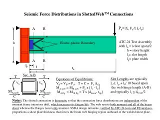
Seismic Force Distributions in SlottedWeb TM Connections. P u = Z b F y /[ l b -l p ]. A. B. ATC-24 Test Assembly with l b = (clear span)/2 h = story height l s = slot length l p = plate width. h. Elastic-plastic Boundary. A. B. l p. l s. l b.

E N D
Seismic Force Distributions in SlottedWebTM Connections Pu= Zb Fy /[ lb-lp] A B ATC-24 Test Assembly with lb = (clear span)/2 h = story height ls= slot length lp= plate width h Elastic-plastic Boundary A B lp ls lb Sec. A-B T T Slot Lengths are typically ls< lp + lb/ 10 based upon the web hinge length (A-B) and typically ls< dbeam/2 Equations of Equilibrium: VA = VB = Pu; T = C = Fy Aflg MA,web = MB,web + Pu x [ ls - lp ] MA,flg = M B,flg = T x [dbeam- tflg] VA VB MA,web MB,web C C Notes:The slotted connection is kinematic so that the connection force distributions are independent of the moment frame interstory drift, which increases its fatigue life. The web resists both moment and all of the beam shear whereas the flanges resist only moment. SSDA design rationale, verified by ATC-24 tests and FE analyses, proportions a shear plate thickness that forces the beam web hinging region outboard of the welded shear plate.