Download
1 / 19
200 likes | 442 Views
Explore the advantages of Class D amplifiers, compare different devices, understand Class D architecture, and analyze matching and simulation results for ideal narrow-band and broad-band applications. Learn about the characteristics of Class D PA, device comparisons, load-pull techniques, and recommendations for optimal performance. Address challenges such as filtering unwanted signals, improving efficiency, and enhancing performance at different frequency bands. This comprehensive guide provides valuable insights into designing high-quality Class D power amplifiers using ADS software.

E N D
Class D Power amplifier-----using ADS Song lin @utk June30
Outline • Why select Class D? • Compare different device • Simple Class D architecture • Load-pull to give out Zout • Matching and simulation results of ideal narrow band Class D PA • Broad band matching
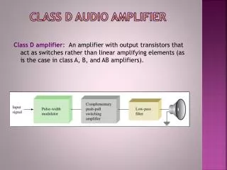
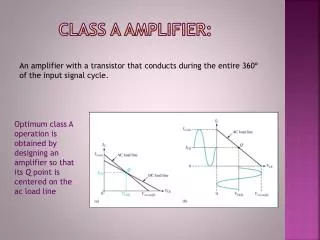
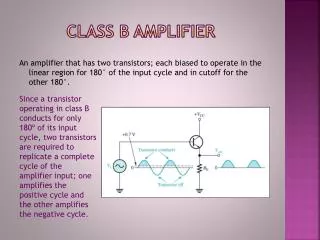
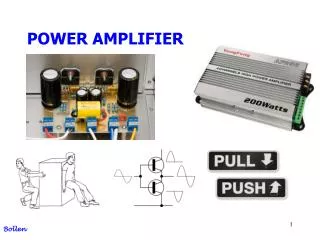
Why Class D? • Class D PA works in the switching mode, with a square wave voltage and a half wave rectified sine wave of current. • In its ideal switching mode, when Vds<>0, Ids=0; when Ids<>0,Vds=0. • Class D PA can achieve very high frequency close to 100%. Although it is very nonlinear, we still can use the LINC technique to kill the IMD product.
Compare the device(I) • For high frequency, ----- the higher the better • For high on/off switching speed,----- the shorter the better • For high efficiency, the on-resistance of a switching device must be as low as possible to minimize the power dissipation in the switches during the positive half cycle.----- Rs is the smaller the better. • For high Power output, ----- BV(beake down voltage) the higher the better • For high Gain, ----- the bigger the better • For power dissipate,----- the small the better
Compare the device(II) Conclusion: Also for the wide band application, we should chose the component whose Zout and Zin has very little variety in some frequency range. I suggest to use the MRF282SR1.-----N-channel Enhancement-Mode Lateral MOSFETs
Narrow band input and output matching and simulation results
Wide band matching using coaxial A conventional design allows the coaxial transformer to transform the impedance to obtain a match the low end of the band, then add additional low-pass matching sections to lower the impedance at the upper band edge.
The problem remain: • The Class D PA need a resonator tank to pull out the fundamental signal, to filter out the third time signal, so I decide to divide the band into 3 parts, one from 30 to 88 MHz; 88MHz to 200MHz; 200MHz to 500MHz. We can separate the signals by filter bank. • For the real device, the Rs isn’t very small, so the efficiency can’t be so high. Because of the , the Vds and some overlap with Ids, it also kill some efficiency. • To achieve better performance at low frequency band, I have to increase the Vgg. • ADS is very hard to converge when simulation.