Download
1 / 17
170 likes | 351 Views
Class-D Garage Band Amplifier. Team: Aaron Danielson, Robert Mann, Randall Newcomb, Scott Russell Sponsor: Nigel Thompson. Overview. The Purpose of the Class-D Garage Band Amplifier Requirements and Stretch Goals System Concept System Block Diagram Sampling and Bitrate Constraints

E N D
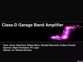
Class-D Garage Band Amplifier Team: Aaron Danielson, Robert Mann, Randall Newcomb, Scott Russell Sponsor: Nigel Thompson
Overview • The Purpose of the Class-D Garage Band Amplifier • Requirements and Stretch Goals • System Concept • System Block Diagram • Sampling and Bitrate Constraints • Task Breakdown • Budget • Project Schedule
Purpose • Class D Amplifier Power Efficiency • Price Point • Open Source • Customizability
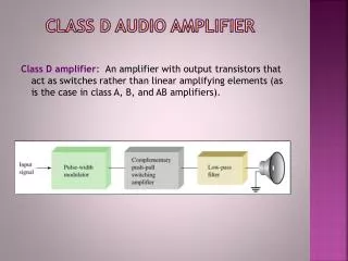
Requirements • An amplifier output will be driven by an FPGA • The output stage will be a PWM H-bridge amplifier • High quality audio • Low cost • High efficiency • Analog Input • Output of more than 100W • 4-Layer PCB • …
Stretch Goals • An enclosure will be constructed to house the amplifier, FPGA and speaker • An alternate amplifier will be implemented • Digital Input Stretch Goal Required PWM Analog In Digital In PSU PSU
System Concept Pre-Filter Images from Google Image
Description of Major Tasks • Design a Top Level Testbench • Contains all the modules for testing that will be synthesized onto the FPGA. • Instantiate PacoblazeuP and write necessary assembly in test environment to reduce synthesize time later. • Digital Signal Processor • Design 2 filters – one each for bass & treble. • Interface with state machine to allow user to adjust settings. • Hardware State Machine • Implement a menu system to control all the systems. • Integrate the uP communication with the state machine for user feedback through the LCD and buttons • Amplifier • Produce a breakout board for inintial testing • Layout custom PCB • Implement final design and test the output stage • Speaker Enclosure • Build the enclosure • Design bandpass filters for the selected speaker