
Comprehensive Guide to Beam and Shaft Design for Bending and Shear Loads
E N D
Presentation Transcript
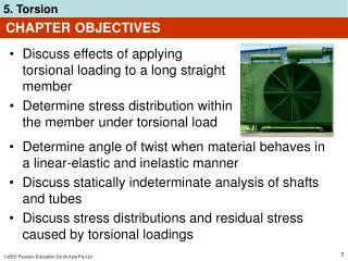
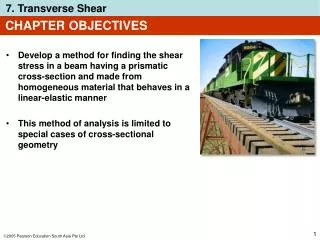
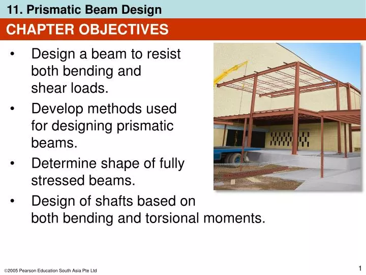
CHAPTER OBJECTIVES • Design a beam to resist both bending and shear loads. • Develop methods used for designing prismatic beams. • Determine shape of fully stressed beams. • Design of shafts based on both bending and torsional moments.
CHAPTER OUTLINE • Basis for Beam Design • Prismatic Beam Design • *Fully Stressed Beams • *Shaft Design
11.1 BASIS FOR BEAM DESIGN • Beams are structural members designed to support loadings perpendicular to their longitudinal axes. • Under load, internal shear force and bending moment that vary from pt to pt along axis of beam. • Axial stress is ignored in design, as it’s much smaller than the shear force and bending moment. • A beam designed to resist shear and bending moment is designed on the basis of strength. • We use the shear and flexure formulae from chapters 6 and 7 to design a beam, only if the beam is homogeneous and displays linear-elastic behavior.
11.1 BASIS FOR BEAM DESIGN • As shown, external distributed and pt loads applied to a beam is neglected when we do stress analysis. • Advanced analysis shows that the maximum value of such stresses are of a small percentage compared to bending stresses. • Also, engineers prefer to design for bearing loads rather than pt loads to spread the load more evenly.
11.2 PRISMATIC BEAM DESIGN • The actual bending and shear stresses must not exceed the allowable values specified in structural and mechanical codes of practice. • We need to determine the beam’s section modulus. Using flexure formula, = Mc/I, we have • M is determined from the beam’s moment diagram, and allowable bending stress, allow is specified in a design code.
11.2 PRISMATIC BEAM DESIGN • Once Sreq’d is known, we can determine the dimensions of the x-section of the beam. • However, for beams with x-section consisting of various elements (e.g. wide-flange section), then an infinite no. of web and flange dimensions can be computed. • In practice, the engineer will choose a commonly-manufactured standard shape from a handbook that satisfies S > Sreq’d.
11.2 PRISMATIC BEAM DESIGN • Use symmetric x-section if allowable bending stress is the same for tension and compression. • Otherwise, we use an unsymmetrical x-section to resist both the largest positive and negative moment in the span. • Once beam selected, use shear formula allow = VQ/It to check that the allowable shear stress has not been exceeded. • Exceptional cases are when the material used is wood.
11.2 PRISMATIC BEAM DESIGN Fabricated Beams 1. Steel sections • Most manufactured steel beams produced by rolling a hot ingot of steel till the desired shape is produced. • The rolled shapes have properties that are tabulated in the American Institute of Steel Construction(AISC) manual. (Appendix B) • Wide flange shapes defined by their depth and weight per unit length.
11.2 PRISMATIC BEAM DESIGN Fabricated Beams 1. Steel sections • Other properties are the dimensions, x-sectional area, moment of inertia, section modulus, and the radius of gyration r, which is related to the section’s buckling strength. • Other sections include channels and angles.
11.2 PRISMATIC BEAM DESIGN Fabricated Beams 2. Wood sections • Most wooden beams are of rectangular x-section due to ease of manufacture and handling. • The nominal and actual dimensions are reported in the manuals. • Nominal dimensions are used to identify the sections while the actual dimensions are smaller due to sawing down the rough surfaces. • Actual dimensions are to be used when performing stress calculations.
11.2 PRISMATIC BEAM DESIGN Fabricated Beams 3. Built-up Sections • A built-up section is constructed from two or more parts joined together to form a single unit. • Based on Eqn 11-1, the moment-resisting capacity of such a section will be greatest for the greatest moment of inertia. • Thus, most of the material should be built furthest from the neutral axis.
11.2 PRISMATIC BEAM DESIGN Fabricated Beams 3. Built-up Sections • For very large loads, we use a deep I-shaped section to resist the moments. • The sections are usually welded or bolted to form the built-up section.
11.2 PRISMATIC BEAM DESIGN Fabricated Beams 3. Built-up Sections • Wooden box beams are made from plywood webs and larger boards for the flanges. • For very large spans, glulam beams are used. Such members are made from several boards glue-laminated together.
11.2 PRISMATIC BEAM DESIGN IMPORTANT • Beams support loadings that are applied perpendicular to their axes. • If they are designed on the basis of strength, they must resist allowable shear and bending stresses. • The maximum bending stress in the beam is assumed to be much greater than the localized stresses caused by the application of loadings on the surface of the beam.
11.2 PRISMATIC BEAM DESIGN Procedure for analysis Shear and moment diagrams • Determine the maximum shear and moment in the beam. This is often done by constructing the beam’s shear and moment diagrams. • For built-up beams, shear and moment diagrams are useful for identifying regions where the shear and moment are excessively large and may require additional structural reinforcement or fasteners.
11.2 PRISMATIC BEAM DESIGN Procedure for analysis Average normal stress • If beam is relatively long, it is designed by finding its section modulus using the flexure formula,Sreq’d = Mmax/allow. • Once Sreq’d is determined, the x-sectional dimensions for simple shapes can then be computed, since Sreq’d = I/c. • If rolled-steel sections are to be used, several possible values of S may be selected from the tables in Appendix B.
11.2 PRISMATIC BEAM DESIGN Procedure for analysis Average normal stress • Choose the one with the smallest x-sectional area, since it has the least weight and is therefore the most economical. Shear stress • Normally, beams that are short and carry large loads, especially those made of wood, are first designed to resist shear and later checked against the allowable-bending-stress requirements.
11.2 PRISMATIC BEAM DESIGN Procedure for analysis Shear stress • Use the shear formula to check to see that the allowable shear stress is not exceeded; allow≥VmaxQ/It. • If the beam has a solid rectangular x-section, the shear formula becomes allow≥ 1.5(Vmax/A), Eqn 7-5, and if the x-section is a wide flange, it is OK to assume that shear stress is constant over the x-sectional area of the beam’s web so that allow≥ Vmax/Aweb, where Aweb is determined from the product of the beam’s depth and the web’s thickness.
11.2 PRISMATIC BEAM DESIGN Procedure for analysis Adequacy of fasteners • The adequacy of fasteners used on built-up beams depends upon the shear stress the fasteners can resist. • Specifically, the required spacing of nails or bolts of a particular size is determined from the allowable shear flow, qallow= VQ/I, calculated at pts on the x-section where the fasteners are located.
EXAMPLE 11.1 A steel beam has an allowable bending stress of allow = 170 MPa and an allowable shear stress of allow = 100 MPa. Select an appropriate W shape that will carry the loading as shown.
EXAMPLE 11.1 (SOLN) Shear and moment diagrams Support reactions calculated, and shear and moment diagrams are shown.From diagrams, Vmax = 90 kN and Mmax = 120 kN·m.
EXAMPLE 11.1 (SOLN) Bending stress Required section modulus for the beam: Using table in Appendix B, following beams are OK:
EXAMPLE 11.1 (SOLN) WE choose the beam having the least weight per meter: W46060. The actual maximum moment Mmax (incl. weight of beam) can be computed and the adequacy of the selected beam can be checked. Comparing with the applied loads, the beam’s weight, (60.35 kg/m)(9.81 N/kg)(6 m) = 3552.2 N = 3.55 kN, will only slightly increase Sreq’d. Thus,
EXAMPLE 11.1 (SOLN) Shear stress Since beam is a wide-flange section, the average shear stress within the web will be considered. Here the web is assumed to extend from the very top to the very bottom of the beam. From Appendix B, for a W1840, d = 455 mm, tw = 8 mm, thus Use a W46060.
EXAMPLE 11.3 Laminated wooden beam supports a uniform distributed loading of 12 kN/m. If the beam is to have a height-to-width ratio of 1.5, determine its smallest width. The allowable bending stress is allow = 9 MPa and the allowable shear stress is allow = 0.6 MPa. Neglect the weight of the beam.
EXAMPLE 11.3 (SOLN) Shear and moment diagrams Support reactions at A and Bhave been calculated and the shear and moment diagrams are shown. Here, Vmax = 20 kN, Mmax = 10.67 kNm.
EXAMPLE 11.3 (SOLN) Bending stress Applying the flexure formula yields, Assume that width is a, then height is h = 1.5a. Thus,
EXAMPLE 11.3 (SOLN) Shear stress Applying shear formula for rectangular sections (special case of max = VQ/It), we have
EXAMPLE 11.3 (SOLN) Equation Since shear criterion fails, beam must be redesigned on the basis of shear. This larger section will also adequately resist the normal stress.
*11.3 FULLY STRESSED BEAMS • To reduce a beam’s weight, engineers sometimes choose a beam having variable x-sectional area, such that at each x-section, bending stress reaches its maximum allowable value. • Such beams are called nonprismatic beams. Examples shown here.
*11.3 FULLY STRESSED BEAMS • In general, the size of the x-section of a nonprismatic beam that supports a given loading can be determined using the flexure formula as • A beam designed in this manner is called a fully stressed beam.
EXAMPLE 11.4 Determine the shape of a fully stressed, simply supported beam that supports a concentrated force at its center. The beam has a rectangular x-section of constant width b, and allowable stress is allow.
EXAMPLE 11.4 (SOLN) The internal moment in the beam, expressed as a function of position, 0 ≤ x < L/2, Hence, required section modulus is Since S = I/c, then for a x-sectional area h by b, we have
EXAMPLE 11.4 (SOLN) If h = h0 at x = L/2, then So that By inspection, depth h must vary in a parabolic manner with distance x. In practice, this shape is the basis for design of leaf springs used to support the rear-end axles of most heavy trucks. Note that although this result indicates that h = 0 atx = 0, it’s necessary that beam resist shear stress at the supports, that is, h > 0 at the supports.
*11.4 SHAFT DESIGN • Shafts with circular x-section are used in many types of mechanical equipment and machinery. • Thus, they are subjected to cyclic or fatigue stress, caused by the combined bending and torsional loads they must transmit. • Stress concentrations will also occur due to keys, couplings, and sudden transitions in its x-sectional area.
*11.4 SHAFT DESIGN • For example, we can resolve and replace the loads with their equivalent components. • Bending-moment diagrams for the loads in each plane can be drawn and resultant internal moment at any section along shaft is determined by vector addition, M = √(Mx2 + Mz2).
*11.4 SHAFT DESIGN • In addition, the torque diagram can also be drawn. • Based on the diagrams, we investigate certain critical sections where the combination of resultant moment M and torque T creates the worst stress situation. • Then ,we apply flexure formula using the resultant moment on the principal axis of inertia.
*11.4 SHAFT DESIGN • In general, critical element D (or C) on the shaft is subjected to plane stress as shown, where
*11.4 SHAFT DESIGN • Using the stress-transformation Eqn. 9-7, we have • Since I = c4/2 and J = c4/2,
*11.4 SHAFT DESIGN • Solving for radius of the shaft, we get
*EXAMPLE 11.6 Shaft is supported by smooth journal bearings at A and B. Due to transmission of power to and from the shaft, the belts on the pulleys are subjected to the tensions shown. Determine the smallest diameter of the shaft using the maximum-shear-stress theory, with allow = 50 MPa.
EXAMPLE 11.6 (SOLN) Support reactions are calculated and shown on the free-body diagram of the shaft.
EXAMPLE 11.6 (SOLN) Bending-moment diagrams for Mx and Mz are also shown here.
EXAMPLE 11.6 (SOLN) Torque diagram is also shown.
EXAMPLE 11.6 (SOLN) By inspection, critical pts for bending moment occur either at C or B. Also, just to the right of C and at B the torsional moment is 7.5 N·m. At C, resultant moment is Whereas at B it is smaller,
EXAMPLE 11.6 (SOLN) Since the design is based on the maximum-shear-stress theory, Eqn 11-2 applies. The radical √(M2 + T2) will be the largest at section just to the right of C. We have
EXAMPLE 11.6 (SOLN) Thus the smallest allowable diameter is
CHAPTER REVIEW • Failure of a beam occurs when the internal shear or moment in the beam is a maximum. • To resist these loadings, it is important that the associated maximum shear and bending stress not exceed allowable values as stated in codes. • Normally, the x-section of a beam is first designed to resist the allowable bending stress, then the allowable shear stress is checked. • For rectangular sections, allow≥ 1.5 (Vmax/A). • For wide-flange sections, we use allow ≥ Vmax/Aweb.
CHAPTER REVIEW • For built-up beams, the spacing of fasteners or the strength of glue or weld is determined using an allowable shear flow, qflow = VQ/I. • Fully stressed beams are nonprismatic and designed such that each x-section along the beam will resist the allowable bending stress. This will define the shape of the beam. • A mechanical shaft generally is designed to resist both torsion and bending stresses.
CHAPTER REVIEW • Normally, bending can be resolved into two planes, and so it is necessary to draw the moment diagrams for each bending moment component and then select the maximum moment based on vector addition. • Once the maximum bending and shear stresses are determined, then depending upon the type of material, an appropriate theory of failure is used to compare the allowable stress to what is required.