Download
1 / 14
150 likes | 414 Views
ARQUITECTURA DE COMPUTADORAS II. INTERRUPCIONES EN LA IBM PC. POLLING (SONDEO). Carlos Canto Q. ARQUITECTURA DE COMPUTADORAS II. INTERRUPCIONES EN LA IBM PC. INTERRUPCIONES. Carlos Canto Q. ARQUITECTURA DE COMPUTADORAS II. INTERRUPCIONES EN LA IBM PC. Carlos Canto Q.

E N D
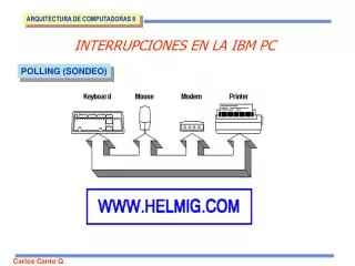
ARQUITECTURA DE COMPUTADORAS II INTERRUPCIONES EN LA IBM PC POLLING (SONDEO) Carlos Canto Q.
ARQUITECTURA DE COMPUTADORAS II INTERRUPCIONES EN LA IBM PC INTERRUPCIONES Carlos Canto Q.
ARQUITECTURA DE COMPUTADORAS II INTERRUPCIONES EN LA IBM PC Carlos Canto Q.
ARQUITECTURA DE COMPUTADORAS II INTERRUPCIONES EN LA IBM PC A partir de la IBM AT se incluyen 2 controladores de interrupción, donde el segundo controlador (ESCLAVO) está conectado en cascada a la línea de interrupción 2 del primer controlador ( MAESTRO) . L a líneas de interrupción del segundo controlador están numeradas de 8 a 15. Debido a este “cascadeo”, la línea de interrupción 2 no está disponible. Sin embargo ; para compatibilidad con la PC original, la línea de interrrupción 2 es conectada a al línea 9 del segundo controlador ( tal que, si un dispositivo en la PC es configurado para la interrupción 2, en realidad éste usa la interrupción 9) Carlos Canto Q.
ARQUITECTURA DE COMPUTADORAS II INTERRUPCIONES EN LA IBM PC 3FFF Tenemos 1024 localidades de RAM en la parte más baja de la memoria que permiten 256 vectores de interrupción de 4 bytes cada uno. Tabla de vectores de interrupción IPL 0003 Un vector de interrupción está formado por la dirección ( 2 bytes para CS y 2 bytes para IP) de inicio de la rutina de servicio de la interrupción ISR esto es expresado como: CS:IP IPH 0002 Vector 0 CSL 0001 CSh 0000 TABLA DE VECTORES DE INTERRUPCIÓN Carlos Canto Q.
INTERRUPCIONES EN LA IBM PC ARQUITECTURA DE COMPUTADORAS II Entradas del controlador programable de interrupciones PIC 8259 Carlos Canto Q.
INTERRUPCIONES EN LA IBM PC ARQUITECTURA DE COMPUTADORAS II The interrupt mask register is an eight bit register that lets you individually enable and disable interrupts from devices on the system. This is similar to the actions of the cli and sti instructions, but on a device by device basis. Writing a zero to the corresponding bit enables that device’s interrupts. Writing a one disables interrupts from the affected device. Note that this is non-intuitive. Figure 17.1 provides the layout of the interrupt mask register. Registro de máscara de Interrupción Carlos Canto Q.
INTERRUPCIONES EN LA IBM PC ARQUITECTURA DE COMPUTADORAS II When an interrupt occurs, regardless of source, the 80x86 does the following: 1) The CPU pushes the flags register onto the stack. 2) The CPU pushes a far return address (segment:offset) onto the stack, segment value first. 3) The CPU determines the cause of the interrupt (i.e., the interrupt number) and fetches the four byte interrupt vector from address 0:vector*4. 4) The CPU transfers control to the routine specified by the interrupt vector table entry. After the completion of these steps, the interrupt service routine takes control. When the interrupt service routine wants to return control, it must execute an iret (interrupt return) instruction. The interrupt return pops the far return address and the flags off the stack. Note that executing a far return is insufficient since that would leave the flags on the stack. Carlos Canto Q.
INTERRUPCIONES EN LA IBM PC ARQUITECTURA DE COMPUTADORAS II The PICs interface to the system through four I/O locations: ports 20h/0A0h and 21h/0A1h. The first address in each pair is the address of the master PIC (IRQ 0-7), the second address in each pair corresponds to the slave PIC (IRQ 8-15 ). Port 20h/0A0h is a read/write location to which you write PIC commands and read PIC status, we will refer to this as the command register or the status register. The command register is write only, the status register is read only. They just happen to share the same I/O location. The read/write lines on the PIC determine which register the CPU accesses. Port 21h/0A1h is a read/write location that contains the interrupt mask register, we will refer to this as the mask register. Choose the appropriate address depending upon which interrupt controller you want to use. Carlos Canto Q.
INTERRUPCIONES EN LA IBM PC ARQUITECTURA DE COMPUTADORAS II Carlos Canto Q.
D 34-37 IRQ5, LPT2, Parallel port hardware (Hard Disk on XT) E 38-3B IRQ6, Floppy Disk adaptor F 3C-3F IRQ7, LPT1, Parallel port hardware 10 40-43 Video services, see note 1 11 44-47 Equipment check 12 48-4B Memory size determination 13 4C-4F Floppy I/O routines 14 50-53 Serial port I/O routines 15 54-57 PC used for Cassette tape services 16 58-5B Keyboard I/O routines 17 5C-5F Printer I/O routines 18 60-63 Points to basic interpreter in a "real" IBM PC 19 64-67 Bootstrap loader 1A 68-6B Time of day services INTERRUPCIONES EN LA IBM PC ARQUITECTURA DE COMPUTADORAS II Carlos Canto Q.
1B 6C-6F Services Ctrl-Break service 1C 70-73 Timer tick (provides 18.2 ticks per second) 1D 74-77 Video parameters 1E 78-7B Disk parameters 1F 7C-7F Video graphics 20 80-83 Program termination (obsolete) 21 84-87 All DOS services available through this Interrupt 22 88-8B Terminate address 23 8C-8B Ctrl-Break exit address 24 90-93 Critical error handler 25 94-97 Read logical sectors INTERRUPCIONES EN LA IBM PC ARQUITECTURA DE COMPUTADORAS II Carlos Canto Q.
26 98-9B Write logical sectors 27 9C-9F Terminate and stay resident routines (obsolete) 28 to 3F A0-A3 to FC-FF Reserved for DOS 40 to 4F 100-103 to 13C-13F Reserved for BIOS 50 140-143 Reserved for BIOS 51 144-147 Mouse functions 52 to 59 148-14B to 164-167 Reserved for BIOS 5A 168-16B Reserved for BIOS 5B 16C-16F Reserved for BIOS 5D 174-177 Reserved for BIOS 5E 178-17B Reserved for BIOS 5F 17C-17F Reserved for BIOS 60 to 66 180-183 to 198-19B Reserved for User programs 67 19C-19F Used for EMS functions INTERRUPCIONES EN LA IBM PC ARQUITECTURA DE COMPUTADORAS II Carlos Canto Q.
68 to 6F 1A0-1A3 to 1BC-1BF Unused 70 1C0-1C3 IRQ8, ISA bus Real time clock 71 1C4-1C7 IRQ9, takes the place of IRQ2 72 1C8-1CB IRQ10 (available hardware interrupt) 73 1CC-1CF IRQ11 (available hardware interrupt) 74 1D0-1D3 IRQ12 (available hardware interrupt) 75 1D4-1D7 IRQ13, maths co-processor 76 1D8-1DB IRQ14, ISA bus hard disk controller 77 1DC-1DF IRQ15, (available hardware interrupt) 78 to 7F 1E0-1E3 to 1FC-1FF Unused 80 to 85 200-203 to 214-217 Reserved for basic 86 to F0 218-21B to 3C0-3C3 Used by basic F1 to FF 3C4-3C7 to 3C4-3FF Unused INTERRUPCIONES EN LA IBM PC ARQUITECTURA DE COMPUTADORAS II Carlos Canto Q.