Download
1 / 26
260 likes | 438 Views
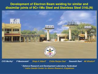
NARROW GAP TIG WELDING AND DEVELOPMENT OF FILLER WIRES OF RAFMS FOR WELDING. G. SRINIVASAN SHAJU K. ALBERT A.K. BHADURI Materials Technology Division Indira Gandhi Centre for Atomic Research Kalpakkam-603102, India. Background.

E N D
NARROW GAP TIG WELDING AND DEVELOPMENT OF FILLER WIRES OF RAFMS FOR WELDING G. SRINIVASAN SHAJU K. ALBERT A.K. BHADURI Materials Technology Division Indira Gandhi Centre for Atomic ResearchKalpakkam-603102, India
Background • RAFM steels are the candidate structural materials for TBM to be installed in the ITER Fusion Reactor. • RAFM steels have a chemical composition similar to modified 9Cr-1Mo steel. • Mo and Nb that produce long living radioactive isotopes in the reactor environment are replaced with W and Ta. • Temperature window for use of these steels are presently about 350–550°C • Lower value being limited by irradiation-induced embitterment effects • Upper value by a strong reduction in mechanical strength.
Objectives • To develop and qualify procedures for joining of various components of TBM using RAFM steel • Narrow Gap TIG • Laser • Electron Beam • Hybrid Laser • Diffusion bonding • To develop consumables for NG-TIG and hybrid laser • To choose suitable joining process based on • Joint Design • Accessibility • Assembly sequence
Requirements of Weld Joints in TBM Fabrication • Microstructure of the joint shall be resistant to the effects of neutron irradiation in the temperature range of 350-550°C • No significant shift in Ductile Brittle Transistion Temperature • Joint should possess required strength, fracture toughness, creep and fatigue resistance to ensure adequate structural stability throughout the service • Fusion welds on the first wall facing plasma is not acceptable
Other Considerations in the Choice of the Welding Process • Minimize the size of the fused metal zone and heat affected zone in the fabricated components • Minimum distortion and low residual stress in the weld • Minimize the use of edge preparation and filler wires • Suitable for the joint configuration and assembly sequence chosen
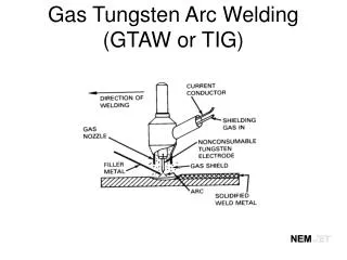
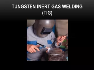
TIG • Arc welding process, uses a nonconsumable tungsten electrode to produce the weld. • Weld area is protected from atmospheric contamination by an inert gas and a filler metal is normally used • Autogenous welds do not require FM • Most commonly used to weld thin sections of SS and light metals
NG-TIG • NG-TIG is an advanced technique for higher productivity in the manufacture of thick-walled components • Developed to achieve similar corrosion and fatigue properties for both weld and base metals without porosity or inclusions • Electrode will be oscillated in the narrow groove by twisting the torch tip in which the tungsten electrode tilted and the pulse energizes and preheats the filler wire prior to its contact the weld puddle.
NG-TIG • Excellent mechanical properties- comparable to BM • Ensures high weld quality and high efficiency • Volume of weld metal deposited and total heat input teo the weld are lower than in conventional TIG • Results in a favorable residual stress profile in the HAZ • NG-TIG technique is considered for the fabrication of the various components of TBM especially in site welding where other joining techniques cannot used. • For PFBR steam generator fabrication this welding process is chosen by the fabricators instead of a combination of TIG and shielded metal arc welding (SMAW) proposed. • Ease of Automation
Schematic of hot wire NG-TIG • Oscillation of the torch tip to ensure side wall fusion • Avoiding use of SMAWprocess, which has low weld metal toughness
TIG (Eurofer) TIG JOINT DESIGN FOR HORIZONTAL/VERTICAL STIFFEENING PLATES
TIG (Eurofer) • FZ: Equiaxed grains of martensite laths • No δ ferrite • G/size 40-100µ • No defects like cracks and inclusions Cross Section view of TIG weld
PEFA-TIG flux developed for single-pass autogenous welding Weld bead penetration of upto 12 mm achieved Specific Advantages Upto 50% in welding costs in bevel preparation in no. of weld passes in welding times in filler wire consumption Distortion in heat input Straight edges No back gouging or grinding Full penetration in single pass Diffused arc in Normal-TIG Constricted arcin PEFA-TIG 12 mm Weld bead shapein Normal TIG Weld bead shapein PEFA-TIG Improvisations in TIG Welding – Penetration Enhancing Flux Assisted (PEFA) TIG Welding (Patented)
PEFA-TIG Welded 9 mm thick 316LN SS Square-Butt Joint Top face Bottom face
TIG – Comparison with other Processes • HAZ width is high -3mm • Distortion noticed • Filler addition is required for more than 3mm thickness • Preheating and post heating generally employed • Residual stress would be high • Very low welding speed • Suitable for site welding • All position welding • Wide experience is available
Other Concerns with respect to Joining • Use of preheating and post heating • Post Weld Heat Treatment (730-760/2h) • It is essential, but extreme care shall be taken to ensure dimensional stability of the components and cooling channels • For hybrid welding, solid state laser welding machine with fiber delivery may be required • Dissimilar welds involving RAFMS and 316L will have microstructure and properties different from the base metals
Development of RAFMS Filler Wires Requirements: • Sound structural welds • Free from cracks • High joint efficiency • Low pore levels • Amenable to automation • in a spool form for both NG-TIG & Hybrid Laser welding
Characterisation Required Tests: • Chemical Composition • Soundness as per AWS SFA 5.28 • Mechanical Property • All Weld Tensile at RT and at 550°C • DBTT <-45°C
Mechanical Properties (RT) * Achieved
Mechanical Properties (550°C) * Achieved
WM <-45°C BM <-70°C EUROFER Below RT <-50°C (for both BM&WM) DBTT
Summary • It is possible to develop welding procedure to produce defect free welds of RAFMS using any of the processes considered for TBM fabrication. • Indigenous development of filler wire is feasible and M/s MIDHANI has the technology for melting and wire drawing • Challenge would be actual fabrication • Joint design • Assembly sequence • PWHT • Distortion • Mock up trails shall be carried out for actual joint configuration and fabrication procedure established before component fabrication is taken up (including heat treatment) • Weld joints needs to be characterised in detail for dissimilar joints involving austenitic stainless steels and RAFMS and produced by EB or Laser Welding without filler addition.