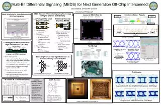
Hierarchical Error Correction Codes over Multi-Bit Differential Signaling
240 likes | 415 Views
Hierarchical Error Correction Codes over Multi-Bit Differential Signaling. Jason D. Bakos. Goals. High performance electrical chip-to-chip signaling. chip 2. PCB traces. PCB traces. chip 3. chip 1. Processor-Memory interconnect Other chip-to-chip interconnect

Hierarchical Error Correction Codes over Multi-Bit Differential Signaling
E N D
Presentation Transcript
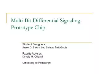
Hierarchical Error Correction Codes over Multi-Bit Differential Signaling Jason D. Bakos
Goals • High performance electrical chip-to-chip signaling chip 2 PCB traces PCB traces chip 3 chip 1 • Processor-Memory interconnect • Other chip-to-chip interconnect • High-resolution digital displays • Storage devices • High-speed sensors
Source: Intel Corporation The Off-Chip Signaling Problem • Growing gap between on-chip core logic speed and off-chip signaling speed
Packaged chip PCB trace Ground plane Challenges for Off-chip Signaling Packaged chip • High-speed links must be narrow • I/O pads are a precious resource in chip design • Skin effect causes high-speed drivers to be large • Integrity of high-speed off-chip signals • capacitance, inductance (METAL) • effect of noise • synchronization • Solution: • Couple data encoding to circuit design
Multi-Bit Differential Signaling (MBDS) • Differential signaling (LVDS) • MBDS • Data encoded as • {01} or {10} • Advantages • Low driver switching noise • No reference noise • Coupled transmission lines • Low voltage swing (low noise) • Disadvantages • Two wires for each bit • Code rate = bits / channels • Data encoded with fixed number of ones • N-choose-M (nCm) • {0011}, {0101}, {0110}, {1001}, {1010}, {1100} • Advantages • Same SNR as differential • Higher code rate than differential
nCm Coding EXAMPLE 6-wire MBDS channel code size = 20 codes effective bits = 4 equivalent to 8-wire differential channel 25% fewer pads (8 versus 6) 25% less power (4 1-bits on versus 3) 125% code capacity (20 codes versus 16) Code set size Effective bits
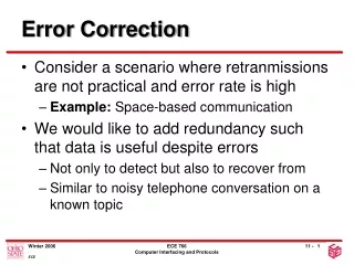
Outline • Use of extra code space for “free” error control mechanism • Sources of channel errors • Introduction to linear block codes • Hierarchical error correction codes • nCm code set partitioning • Encoding mechanism • Decoding mechanism • Code rate computation for HECC codes • Analysis of single-channel correcting codes • Analysis of multiple-channel correcting codes • Future Work
Sources of Channel Errors • Jitter and channel noise cause channel errors at high transmission rates • Need a way to recover from channel errors • 4c2 channel at 2.5 Gb/s • 4c2 channel at 10 Gb/s
Odd-number of channel errors 1011 1101 0111 1110 0011 0001 1000 0010 0100 1 error 3 errors • Even-number of channel errors 0011 1111 1001 1001 1010 0101 0110 0000 nCm Codes: Natural Error Detection • nCm codes have inherent error detection
Exploit by using 2 nCm drivers in parallel as bus 6 cw 6 cw 36 combinations 5 bits 4c2 4c2 2 bits 2 bits nCm Codes: Extra Code Words • Each nCm code set has unmapped code words • Example • 4c2 (base-6 value) => binary value 0011 00 0101 01 0110 10 1001 11 1010 ? 1100 ?
base-q parity base-q data symbols Linear Block Codes • Use (n,k,q) linear block code • n symbols in block, over base-q alphabet • k data symbols • n-k parity symbols • Can correct erasures and symbol errors • Example (4,3,q) code: • Problems: • Application over nCm symbols too detrimental to overall code rate • Doesn’t take advantage of inherent error detection ability • Lookup table for data too large
1100 0101 0011 0110 1001 1010 Partitioning nCm Code Sets • nCm code sets have distance=2 • Increase distance by partitioning into “distance subsets” • Example • 4c2, distance=4 (correct 1 bit, = floor((distance-1)/2)) • Subsets: • 0 => {0011, 1100} • 1 => {0101, 1010} • 2 => {0110, 1001} • If the subset is known, channel errors may be corrected • First level of hierarchy
Partitioning Problem • How to partition large nCm code sets into distance subsets? • Graph coloring is too complex for large code sets ( > 6c3) • Good news: • Done off-line • Won’t go beyond 8c4 code set • Use heuristic… • Based on pruning depth-first search over space of code word subset assignment
bblock bits bsymbol bits 0101001001 0010010100 Data as subset values Data as code words Parity as subset value(s) Parity as code words Encoding Hierarchical Block Codes b bits 01010010010010010100
Encode 111101… 111 2 1 • Compute checksum parity… 2 1001 1 0101 0 1100 • Encode 101… • 0 => {0011, 1100} • 1 => {0101, 1010} • 2 => {0110, 1001} Example Encoding • Assume 3 x 4c2 drivers • s=3, c=2 • (3,2,3) checksum code • “data” portion • sk = 9 cw (3 bits) • code word decisions, • cn = 8 cw (3 bits) • code rate = 6 bits / 12 channels = 50% • Can correct one channel error
2 1 0 ? 1 0 1001 0101 1100 1101 0101 1100 Decoding HECC Codes • Decoder: • If invalid code word is detected • Determine subset of code word in error • Use minimum distance decoder to determine correct codeword • Assume error occurs… • 0 – 1 = 2 (mod 3) • Symbol in error must be 0110 or 1001 • dist(1101,0110) = 3, dist(1101,1001) = 1 • Corrected symbol is 1001
Computing Code Rate for HECC • Code rate is defined as • Number of data bits / number of channels • In this context, must add data bits encoded into • subset choices • code word choices • We “break even” when code rate matches differential at 50%
Analysis of Checksum-Based Codes • HECC codes defined as • nCm code set • # of parallel drivers • (s,c) • (n,k) • Checksum-based codes can correct one channel error • Fully utilized partitioning • s*c = cw
Analysis of Checksum-Based Codes • Under-utilized partitionings • s * c < cw
Data Parity Block Codes for Correcting Errors • MDS code (Reed-Solomon) • Can correct subset errors: • Number of parity symbols / 2 • Can correct erasures: • Number of parity symbols • Restrictions: • Number of subsets must be prime or power of a prime • Can correct • 1 error • 2 erasures
Analysis of Multiple Channel-Error Codes • 5c2, 7c3 • 2 parity symbols used • MDS-code used until reached limit • After MDS limit, NMDS code used • 6c3 • Code set distance is 6 (t=2) • One parity symbol • 8c4 • Code set distance is 8 (t=3) • One parity symbol
Future Work • Find better codes => higher code rate • Design efficient implementation of encoding / decoding logic
Acknowledgements • Donald Chiarulli, advisor (CS Department) • Steven Levitan, advisor (EE Department)