Download
1 / 19
190 likes | 214 Views
Learn the design principles, chamber layout, material selection, and pumping strategies for high-performance storage ring vacuum systems. Includes insights on aperture precision, pressure control, and absorber placement.

E N D
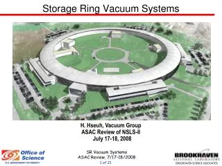
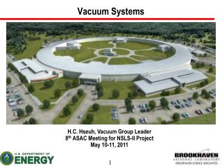
Storage Ring Vacuum Systems H-C. Hseuh, C. Foerster, J. Hu, G. Mahler, S. Pjerov, S. Sharma, J. Skaritka, C. Stelmach, … October 10, 2006 H-C. Hseuh,…, SR Vacuum Systems
Outline Design Principles Vacuum Cell Layout Cell Chambers and Material - Al Chamber Cross Sections and Analysis Vacuum Pumping and Pressure Profiles Front End Vacuum Summary H-C. Hseuh,…, SR Vacuum Systems
Design Principles Adequate Apertures for Beam and Exit Photons • BSC - 25mm x 70mm • Chamber cross section precision to ~1 mm • Chamber temperature stability « 1oC Low Impedance: • Beam channel with smooth cross sections • Minimize no. of tapers, steps, gaps – low Z • Minimize no. of holes, slots for pumps and bellows – low Z/n • Inner wall surface finish to ~ μm Low Pressure of < 1 nTorr (» 50% H2) • Low outgassing and desorption after in-situ bake and pre-conditioning • Intercept photons atdiscrete absorbers • Located absorbers far away from the source • Lower power density and simpler cooling • High effective pumping speed (IP + TSP) at absorber locations H-C. Hseuh,…, SR Vacuum Systems
Vacuum Cell Layout 30 standard cells of ~ 19m eachLSS: 15 x 5m and 15 x 8mIsolatable with 60 gate valves FE Absorber locations 3m 5m 3m 4m 4m Cell chamber material: extruded aluminum 6063-T5 NSLS and APS experience; fabrication cost thermal/electrical conductivity; ease of in-situ baking 60 bending chambers of 6o each, 3m long 90 multipole chambers of 3 different lengths/types > 20 day-one LSS chambers of various types extruded Al with same cross sections as cell chambers H-C. Hseuh,…, SR Vacuum Systems
AL-6063 (T5) Extrusion for the Cell Chamber Comparison of chamber materials H-C. Hseuh,…, SR Vacuum Systems
Fabrication Steps for Cell Aluminum Chambers (G. Goeppner/E. Trakhtenberg, APS, ANL) Material ($): Aluminum 6063-T5 billets, ~ 350mm diameter Extrusion ($): only a few available (interested) vendors in the US (due to the large cross sections and required dimensional precision) ➱> 1 yr to develop the correct parameters for each type before production can start Stretching: to straighten and eliminate the waviness of inner surface Roll Bending ($): to obtain the correct curvature for bending chambers Machining ($$$): ports for beam lines, BPMs, absorbers, pumps, …. profiles at multipole, transitions, … Cleaning ($): to remove surface contaminants and reduce oxide layer Welding ($$): photon exit ports, SS-Al bi-metal flanges, etc. Assembly ($$$): BPMs, NEG strips, pumps, gauges, absorbers, …. H-C. Hseuh,…, SR Vacuum Systems
3-D Models of Cell Chambers Bending chamber, ~ 3m long #3 Multipole magnets/girder Bending magnet/girder Multipole chamber #3, ~ 5m long Special Bending chamber for IR lines H-C. Hseuh,…, SR Vacuum Systems
Chamber cross sections Dipole extruded cross sections 3mm wall BSC: 25 x 70 mm2 H-C. Hseuh,…, SR Vacuum Systems
Chamber cross sections – cont’d BSC: 25 x 70 mm2 Multipole chamber extruded cross section 3.2mm @ sextupole After Machining 3.9mm @ quadrupole H-C. Hseuh,…, SR Vacuum Systems
von Mises stress at sextupole location SM = 172 MPa (Localized) SY = 144 MPa for Al 6063-T5 SM (D) = 54 MPa SM (Q) = 100 MPa Chien Pai, C-AD H-C. Hseuh,…, SR Vacuum Systems
Deflection at sextupole location DM = 0.6mm x 2 DM (Dipole) = 0.36mm x 2 DM (Quad) = 0.57mm x 2 Chien Pai, C-AD H-C. Hseuh,…, SR Vacuum Systems
UHV Pumping and Pressure Profiles Pavg < 1 nTorr In-situ baking of entire cells at 120 C x 40 hrs To reduce thermal outgassing to < 1x10-12 Torr.l/s/cm2 Total ring thermal gas load of < 1x10⁻⁵ Torr.l/s Pressure will be dominated by photon stimulated desorption (PSD) # photonsfrom BM ~ 1x10+21/s ≈ 7x10⁻⁵ Torr.l/s Assuming η (PSD) = 2x10⁻⁶ mol/hv for Cuafter ∫hv > 1024/m # photonsfrom each 7m DW ~ 6x10+20/s with 15% intercepted by the ring absorber ➱7x10⁻⁶ Torr.l/s NEG strips ~ 1,400 m @ > 100 l/s/m for active gases Reside in ante-chambers as in APS Pump thru the photon slots ( C = ~ 200 l/s/m) Ion pumps and TSP of ~ 500 l/s at absorbers 5 IP/TSP per cell + 2 for each ID location H-C. Hseuh,…, SR Vacuum Systems
PSD Yield versus Photon Dosage measured at NSLS U9A & X28 beam lines Cu Al ~ 100A.hr at NSLS C. Foerster, et.al, J. Vac Sci. Technol. A14, 1273(1996). C. Foerster, et.al, J. Vac Sci. Technol. A19, 1652(2001). H-C. Hseuh,…, SR Vacuum Systems
Pressure Profiles (BM only) with Various Pumping Schemes Using Molflow and VacCal codes By E. Hu & F. Makahleh Distributed NEG strips are critical to achieve low Pavg! Preliminary Pavg ~ 1.5 nTorr Pavg ~ 0.3± 0.1 nTorr H-C. Hseuh,…, SR Vacuum Systems
Pressure Profiles with and w/o Damping Wiggler Radiation By E. Hu & F. Makahleh Preliminary Pavg ~ 0.3 nTorr Pavg ~ 0.27 nTorr Absorber IP/TSP H-C. Hseuh,…, SR Vacuum Systems
Beam Line Front End Vacuum Front end design depends on type of radiation source (BM or ID) base on experience at NSLS and APS Details are being developed with the beam line determination Front End Vacuum Systems Pressure of a few nTorr to protect the UHV SR vacuum from HV beam line with window or differential pumping Entire FE to be bakeable to 200 C (all metal, UHV material, etc) IP/TSP combination (same as SR) at high heat load components PS: photon shutter BS: Bremsstrahlung beam stop IP/TSP:ion pump/titanium sublimation pump GV:gate valve IP/TSP GV BS PS Typical layout of Day 1 front end w/o beam line. H-C. Hseuh,…, SR Vacuum Systems
Typical layout of hard/soft x-ray beam line front end. SS x 2 PM: photon mask; CO: collimator; PS: photon shutter; BDA: beam defining aperture; SS: safety shutter FV BDA GV BPM GV PS BPM CO PM IP/TSP IP/TSP IP/TSP GV: gate valve; FV: fast valve; IP/TSP: ion pump and titanium sublimation pump H-C. Hseuh,…, SR Vacuum Systems
Major Goals for FY07 and FY08: Detail layout of cell and ID chambers, absorbers and pumps Detail design of cell chambers and absorbers Fabricate or acquire (from APS?) a few prototype cell chambers Learn and develop expertise in NSLS-2 chamber fabrication Establish formal collaboration with APS colleagues Work with potential extrusion vendors ASAP Refine the fabrication technique to meet the specifications Perform mechanical and vacuum evaluation on prototype chambers Dimensional precision, support, alignment NEG strip supports and installation Vacuum performance In-situ baking, NEG activation H-C. Hseuh,…, SR Vacuum Systems
Summary Preliminary layout of cell chambers is progressing well Improvements are made together with the lattice Stress and deflection of chambers at multipole locations are acceptable Detail chamber design can be started Ray tracing of SR fan continues to optimize the absorber design Simulation of the pressure profiles has started. Including the PSD gas load from ID devices. To be refined with the final chamber/absorber design Pressure of < 1 nTorr is achievable with present pumping scheme Need to collaborate with APS colleagues on chamber fabrication Need to work with extrusion vendors soon H-C. Hseuh,…, SR Vacuum Systems