Download
1 / 39
390 likes | 414 Views
Learn about sequential circuits, SR latch, clocked SR flip-flops, master-slave designs, VHDL implementations, 7-segment displays, Arduino kits, and edge-triggered flip-flops. Understand excitation tables & TBird Lights project.

E N D
Lec 11Flip Flop Excitation Tables CSCE 211 Digital Design Topics • Sequential Circuits • SR Latch • Clocked SR • Master Slave • Master Slave VHDL Readings: 5.4, 5.9, 5.10, 4.4 October 21, 2015
Overview Last Time • Sequential Circuits: Basic Nor Latch New • Sequential Circuits • Clocked SR flip flops • Master Slave SR • VHDL – two bit adder Arduino • Kits • http://www.arduino.cc/ ; http://arduino.cc/en/Guide/HomePage
Clocked SR-Latch http://www.play-hookey.com/digital/ S1 R1 http://www.play-hookey.com/digital/sequential/clocked_rs_latch.html
Clocked SR-Latch Implementation S Q CP Qbar R 74LS00
Building a JK from Chips 74LS00 74LS10 Vcc CP J K GND Q QN 74LS00
74LS49 – Seven segment display driver 74LS49/74LS47 • Inputs BCD digit (DCBA) (D is the MSB) • Outputs abcdefg – the seven segment driver lines • Schematic fig 5-45 • Note negation of inputs to or-gate • x’ + y’ = (x’ + y’)’ ’ = (x’’ . y’’)’ = (x . y)’ • It’s a NAND! • Truth table fig 5-21
Hints on Circuits Hook up MUX BCD-to-7Seg 7Segment • Steps 1. Vcc,GND to all 2. put 330 ohm resistors in series with anode connections to LSD5061-11 (MAN71A) hooking them to Vcc 3. Test the 7-segment display hooking the individual cathodes to GND 4. Hook up outputs from 74LS47 to cathode inputs of 7-segment display 5. Hook the LampTest (pin 3) of the 74LS47 to GND, all segments should light up. 6. Hook up A1,A0 inputs of 74LS47 to Mux outputs, A2 and A3 should be GND 7. Test various values of select lines and mux inputs
Getting Started with Arduino • Introduction: What Arduino is and why you'd want to use it. • Installation: Step-by-step instructions for setting up the Arduino software and connecting it to an Arduino Uno, Mega2560, Duemilanove, Mega, or Diecimila. • Windows • Mac OS X • Linux (on the playground wiki) • Environment: Description of the Arduino development environment and how to change the default language. • Libraries: Using and installing Arduino libraries. • Troubleshooting: Advice on what to do if things don't work. http://arduino.cc/en/Guide/HomePage
Hooking them Up 74LS153 74LS47 74LS153
J-K Flip Flop J K http://www.play-hookey.com/digital/jk_nand_flip-flop.html
The D Flip Flop One input D D = 0 Q(t+1) = 0 D = 1 Q(t+1) = 1
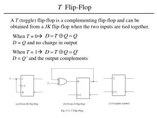
The T Flip Flop One input T T = 0 No change Q(t+1) = Q(t) T = 1 Complement Q(t+1) = Q(t)’
Excitation Tables What inputs do we need to supply to the flip-flop do achieve the desired state transition?
Excitation Tables: JK What inputs do we need to supply to the flip-flop do achieve the desired state transition?
Excitation Tables: T What inputs do we need to supply to the flip-flop do achieve the desired state transition?
Characteristic Equations Next state as a function of current state and inputs Q* = F(Q, S, R) // Q* = Q(t+1) Table 7-1 of text For MS S-R flip-flop Q*
Characteristic Tables and Equations Characteristic Tables for a flip flop Describes next state Q* [or Q(t+1)] as function of inputs and in terms of current state Q [or Q(t)] Characteristic Equation specifies the next state as a function of current state and inputs (as an equation)
Excitation Tables What inputs need to be given to cause a specific state transition?
Edge Triggered D Flip-Flops Positive edge triggered master slave QM D Q C D Q C D CLK Suppose D=0 for sometime then Qm = 0 and Q = 0 Then tracing this through setting D=1, CLK=1 The master changes when the clock CLK goes to 0 This means QM goes to 1, and then when the CLK goes to 1 Q becomes 1
output depends onstate and input typically edge-triggered D flip-flops State-machine structure (Mealy)
output dependson state only typically edge-triggered D flip-flops State-machine structure (Moore)
TBird Lights State machine problem
Bouncing Switches Connecting the “red” terminals below should change the output from 0 to 1. However, this change is not instantaneous; switches bounce • http://www.ganssle.com/debouncing.pdf
Switch Bouncing When contact is made, it is not made instantaneously and smoothly. There is contact, it bounces open, contact again, open again … finally settling down after a few milliseconds (840 μsec = 840*10-6 sec) http://www.ganssle.com/debouncing.pdf
Debouncing with a SR latch Fig 8-6 p 669