Download
1 / 33
350 likes | 563 Views
2.008 Design & Manufacturing II Spring 2004 Metal Cutting II. 2.008-spring-2004 S.Kim . 1. Orthogonal cutting in a lathe. Assume a hollow shaft. Shear plane. Shear angle. T 0 : depth of cut. Rake angle. 2.008-spring-2004 S.Kim . 3. Cutting processes Objectives

E N D
2.008 Design & Manufacturing • II • Spring 2004 • Metal Cutting II 2.008-spring-2004 S.Kim 1
Orthogonal cutting in a lathe Assume a hollow shaft Shear plane Shear angle T0: depth of cut Rake angle 2.008-spring-2004S.Kim 3
Cutting processes • Objectives • Product quality: surface, tolerance • Productivity: MRR , Tool wear • Physics of cutting • Mechanics • Force, power • Tool materials • Design for manufacturing 2.008-spring-2004S.Kim 2
Velocity diagram in cutting zone Cutting ratio: r <1 2.008-spring-2004S.Kim 4
E. Merchant’s cutting diagram Chip Tool Workpiece Source: Kalpajkian 2.008-spring-2004S.Kim 5
FBD of Forces Friction Angle Chip Tool Workpiece Typcially: 2.008-spring-2004S.Kim 6
Analysis of shear strain What does this mean: Low shear angle = large shear strain Merchant’s assumption: Shear angle adjusts to minimize cutting force or max. shear stress Can derive: 2.008-spring-2004S.Kim 7
Shear Angle Chip Tool Workpiece Maximize shear stress Minimize Fc 2.008-spring-2004S.Kim 8
Power Power input : Fc ⋅V => shearing + friction MRR (Material Removal Rate) = w.to.V Power for shearing : Fs⋅Vs Specific energy for shearing : u = MRR Power dissipated via friction: F⋅ Vc Specific energy for friction : uf Total specific energy : us + uf Experimantal data 2.008-spring-2004S.Kim 9
Cutting zone pictures continuous secondary shear BUE Primary shear zone serrated discontinuous Kalpajkian 2.008-spring-2004S.Kim 10
Chip breaker Continuous chip: bad for automation Chip breaker Before Clamp Chip Rake face of tool Chip breaker After - Stop and go - milling Tool Tool Rake face Radius Positive rake 0’ rake 2.008-spring-2004S.Kim 11
Cutting zone distribution Hardness Temperature Chip Chip Temperature Hardness(HK) Tool Workpiece Workpiece Mean temperature: CVafb HSS: a=0.5, b=0.375 2.008-spring-2004S.Kim 12
Built up edge What is it? Why can it be a good thing? Why is it a bad thing? Thin BUE How to avoid it… •Increasing cutting speed •Decreasing feed rate •Increasing rake angle •Reducing friction (by applying cutting fluid) 2.008-spring-2004S.Kim 13
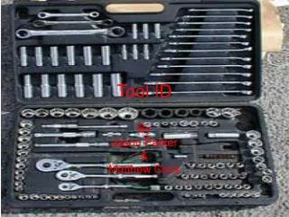
Tools -High T -High σ -Friction -Sliding on cut surface HSS (1-2 hours) Inserts 2.008-spring-2004S.Kim 14
Tool wear up close Depth of cut line Flank wear Wear land Crater wear Rake face Cutting edge Crater wear Flank face Flank wear 2.008-spring-2004S.Kim 15
Taylor’s tool wear relationship (flank wear) F.W. Taylor, 1907 T = time to failure (min) V = cutting velocity (fpm) Workpiece hardness d = depth of cut f = feed rate Tool life (min) Optimum for max MRR? fpm 2.008-spring-2004S.Kim 16
Taylor’s tool life curves (Experimental) m/min Coefficient n varies from: As n increases, cutting speed can be increased with less wear. Cutting speed (ft/min) Given that, n=0.5, C=400, if the V reduced 50%, calculate the increase of tool life? Log scale 2.008-spring-2004S.Kim 17
What are good tool materials? Hardness wear temperature Toughness fracture 2.008-spring-2004S.Kim 18
History of tool materials Diamond, cubic boron nitride Carbon steel Aluminum oxide (HIP) Aluminum oxide+30% titanium carbide Silicon nitride High-speed steel Cermets Cast cobalt-base alloys Coated carbides Machining time (min) Carbides Cemented carbides Hot hardness wear resistance Improved carbide grades HSS First coated grades First double-coated grades First triple-coated grades Year Strength and toughness Trade off: Hardness vs Toughness wear vs chipping 2.008-spring-2004S.Kim 19
HSS High-speed steel, early 1900 Good wear resistance, fracture resistance, not so expensive Suitable for low K machines with vibration and chatter, why? M-series (Molybdenum) Mb (about 10%), Cr, Vd, W, Co Less expensive than T-series Higher abrasion resistance T-series (Tungsten 12-18%) Most common tool material but not good hot hardness 2.008-spring-2004S.Kim 20
Carbides Hot hardness, high modulus, thermal stability Inserts Tungsten Carbide (WC) (WC + Co) particles (1-5 µ) sintered WC for strength, hardness, wear resistance Co for toughness Titanium Carbide (TiC) Higher wear resistance, less toughness For hard materials Uncoated or coated for high-speed machining TiN, TiC, TiCN, Al2O3 Diamond like coating CrC, ZrN, HfN 2.008-spring-2004S.Kim 21
Crater wear Diffusion is dominant for crater wear A strong function of temperature Chemical affinity between tool and workpiece Coating? Crater wear 2.008-spring-2004S.Kim 22
Multi-phase coating Custom designed coating for heavy duty, high speed, interrupted, etc. TiN low friction Al203 thermal stability TiCN wear resistance Carbide substrate hardness and rigidity 2.008-spring-2004S.Kim 23
Ceramics and CBN Aluminum oxide, hardness, high abrasion resistance, hot hardness, low BUE Lacking toughness (add ZrO2, TiC), thermal shock Cold pressed and hot sintered Cermets (ceramic + metal) Al2O3 70%, TiC 30%, brittleness, $$$ Cubic Boron Nitride (CBN) 2nd hardest material brittle Polycrystalline Diamond 2.008-spring-2004S.Kim 24
Range of applications High High 2.008-spring-2004S.Kim 25
Chatter Severe vibration between tool and the workpiece, noisy. In general, self-excited vibration (regenerative) Acoustic detection or force measurements Cutting parameter control, active control Tool Variable chip thickness Workpiece 2.008-spring-2004S.Kim 26
Turning parameters MRR = π Davg. N. d . f N: rotational speed (rpm), f: feed (in/rev), d: depth of cut (in) l; length of cut (in) Cutting time, t = l / f N Torque = Fc (Davg/2) Power = Torque. Ω 1 hp=396000 in.lbf/min = 550 ft.lbf/sec Example 6 inch long and 0.5 in diameter stainless steel is turned to 0.48 in diameter. N=400 rpm, tool in traveling8 in/min, specific energy=4 w.s/mm2=1.47 hp.min/in3 Find cutting speed, MRR, cutting time, power, cutting force. 2.008-spring-2004S.Kim 27
Sol. Davg=(0.5+0.48)/2= 0.49 in V=π. 0.49.400 = 615 in/min d=(0.5-0.48)/2=0.01 in F=8/400=0.02 in/rev MRR=V.f.d=0.123 in3/min Time to cut=6/8=0.75 min P=1.47 x 0.123 = 0.181 hp=Torque x ω 1hp=396000 in-lb/min T=P/ω=Fc. (Davg/2) Then, Fc=118 lbs 2.008-spring-2004S.Kim 28
Drilling parameters MRR: MRR: Power: specific energy x MRR Torque: Power/ω A hole in a block of magnesium alloy, 10 mm drill bit, feed 0.2 mm/rev, N=800 rpm Specific power 0.5 W.s/mm2 MRR Torque 2.008-spring-2004S.Kim 29
Sol MRR=π (10x10/4 ) . 0.2 . 800 =210 mm3/s Power = 0.5 W.s/mm2 . 210 mm3/s =105 W = 105 N.m/s = T.ω =T 2π. 800/60 =1.25 N.m 2.008-spring-2004S.Kim 30
Milling Face milling End milling Slab milling Arbor Cutter Spindle Spindle Shank End mill Arbor Chip continuous? 2.008-spring-2004S.Kim 31
Milling parameters (slab) Parameters: Cutting speed, V=πDN tc, chip depth of cut d; depth of cut f; feed per tooth v; linear speed ofthe workpiece n; number of teeth t; cutting time, w; width of cut Torque: Power/ω Power: sp. Energy x MRR approximation MRR wdv 2.008-spring-2004S.Kim 32
DFM for machining Sharp corners. Hole with large L/D ratio. Geometric compatibility Dimensional compatibility Availability of tools Drill dimensions, aspect ratio Constraints Process physics Deep pocket Machining on inclined faces Set up and fixturing Tolerancing is $$$ Minimize setups Undercut Internal recesses Different blind hole. Requires two setups. Unrnachinable screw threads. 2.008-spring-2004S.Kim 33