Download
1 / 38
390 likes | 503 Views
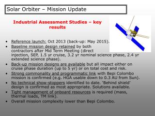
The Solar-B Mission. Tetsuya Watanabe National Astronomical Observatory, Japan National Institutes for Natural Sciences. Mission & Scientific Instruments AOCS ( FOVs and Pointing ) MDP-DHU capabilities (Data Recorder, Data Rates, Flare detection). Mission Scientific Operation

E N D
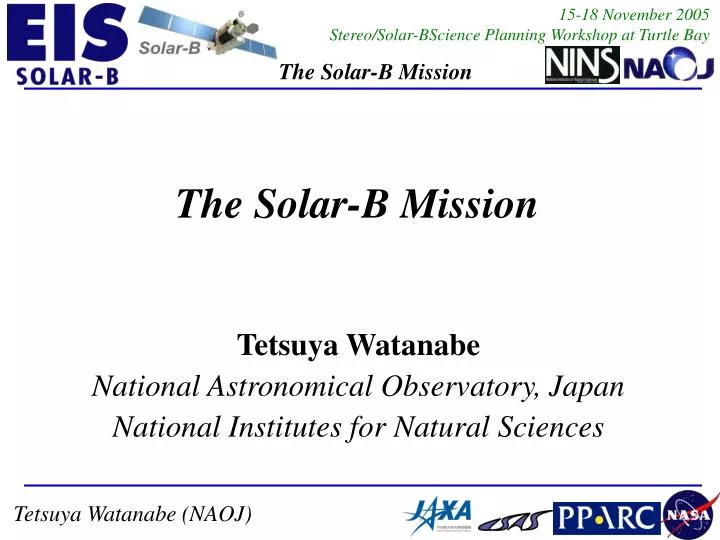
The Solar-B Mission Tetsuya Watanabe National Astronomical Observatory, Japan National Institutes for Natural Sciences
Mission& Scientific Instruments AOCS(FOVs and Pointing) MDP-DHU capabilities (Data Recorder, Data Rates, Flare detection) Mission Scientific Operation Operaton planning & operation Command Uplink Data Downlink Data distribution SVS USC Science Data
Launch: Summer 2006 Sun-synchronous orbit The SOLAR-B Mission
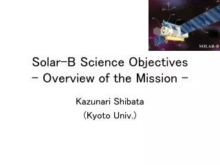
Science Objectives of the Solar-B Mission ACoronal heating chromospheric heating, spicule,,, ACoronal dynamics and structures jets, prominence, CME, solar wind, wave/shock,,, AElementary processes such as reconnection reconnection jet, inflow, slow/fast shocks,,, AEmerging flux and dynamo flux tube, sunspot, convection,,,,
SOT/FG SOT/SP XRT EIS Data control at MDP SOT & XRT via Observation Table observation table in MDP rasters rasters slots obs →time observation table in ICU/EIS
Solar-B instrument specification (=Scientific requirements):
N FOV of the Telescopes Solar disk 320 arcsec SOT E 160 arcsec 512 arcsec EIS 360 arcsec XRT
EIS Shift of FOV center with coarse-mirror motion 800 800 512 512 Raster-scan range 250 slot 40 slot
φ θ pointing target ω0; commandable from the ground in the range of 0.15 – 0.26 rad/day.
Pointing target of the spacecraft θ(t) = θ(t0) & φ(t) = φ(t0) + ωt, where θ and φ are heliospheric latitude and longitude, t is time, and t0 is an epoch, ωis the anglular velocity seen from the earth. As the sun rotates differentially, ωdepends on the heliospheric latitude, and is expressed as follows, using ω0, the angular velocity in the inertia frame. ω = ω0 – Ωe; ω0 = a-b sin2(θ) a = 14.44 deg/day b = 3.0” (Allen, 1973, ‘Astrophysical Quantities’) where Ωe is the angular velocity of revolution of the earth.
Modes of observation N observing wider FOV =tracking area transfer observing the limb = offset A B C change to a new target of observation=a new tracking D synoptic F observing poles=offset SOT FOV E S
Image stability Table Items to be considered for image stability requirements Remark: Specifying with 3σin Item 1 is adopted because it has good correlation with image contrast.
Table Pointing Stability (Ver.4.2):*All numbers are in unit of arcseconds *AR: Active Region、QR: Quiet Region, CH: Corona Hole
Pointing Stability of the spacecraft Short term: 0.7 arcsec/1 sec {0.06arcsec/10sec} 1.1 arcsecs/20 sec Medium term: 1.7 arcsecs/1 min 2 arcesec/20 min Long term: 5 arcsecs/1 hour {2arcsecs/1hour} Mission long: 20 arcsecs achieved by AOCS (body) {+ CTM/TTM (ctm/ttm)}
Data Recorder (DR) Buffer 12Mbps SOT SOT 1400kbps ~2.4Gbits /downlink 64Mbits Bit Comp. + Image Comp. 3Mbps DR XRT 300kbps XRT 8Gbits 64Mbits 2Mbps EIS EIS 300kbps MDP Ground 64Mbits DHU
Simple ring buffers (size~8Gbits) • One partition for SOT, XRT & EIS (+MDP) • One partition for S/C • No priority control • Stop or overwrite @ full (selectable) Record (Write Pointer) Play back (Read Pointer)
4Mbps (X-band) Bottle neck for total amount of data 32kbps(S-band) - For S/C 200 minutes of down-link / day 4 KSC + 15 SVS / day 2.4Gbits/downlink, ave. recording rate 400kbps Down link SVS ==== 2.4G×(#downlinks)
SOT 1400Mbits (70%) FG 1100Mbits (55%) SP 300Mbits (15%) XRT 300Mbits (15%) Partial Frame 225Mbits (11.25%) Full Frame 75Mbits (3.75%) EIS 300Mbits (15%) Sharing of Telemetry (per downlink) • Ratio can be changed
FLD is the function to detect flare occurrence and radiation belts (SAA, HLZ). Detection of Flare occurrence Detection of Radiation Belts Set FL flag and notify FL location to EIS and SOT FLD with flare patrol images in soft X-rays Time resolution : 10 sec – 640 sec Spatial Resolution : 8” (8x8 binning on CCD = 256x256) FLare Detection (FLD)
Mission Operationdaily command uplink Morning Evening deadline Time (15:00JST) Work Area of Science Operation Team at ISAS S/C Chief Planner CMD for S/C SOT - Real-time commands - Commands used in OP - Observation Table OP/OG for S/C OP/OG USC XRT - Real-time commands - Commands used in OP - Observation Table Merger (ISAC-PLN) CMD ISAS EIS - Real-time commands - Commands used in OP - Observation Table satellite operation system TBL
Launch 3 months Initial Observation Plan (Core Science Plan) Baseline Plan Solar-B Team proposers (collaborators) Proposals • “Initial 3-month Observation Plan” during initial three (TBD) months: “Solar-B Core Science Programme” • After the initial three (TBD) months, the initial plans will constitute “baseline” observation plans. Observation plans will be widely proposed and inserted in the “baseline” observation plans.
Database at ISAS KSC Kagoshima, Japan Data conv tool SVS Station Data flow from Solar-B to Level-0 Data: I Example Software Data Hand work W/ software Database
Solar-B Op. DB Level-0 Reformtter Image construction & Add information SOT-FG/SP Level-0 Data Writer SIRIUS Database Level-0 Obs. Data [FITS] XRT Attitude data and Orbital Position EIS Level-0 Writer Level-0 COM data (HK/Status) Data flow from Solar-B to Level-0 Data:III <Level-0 Reformat / Obs. data>
Data flow after downlink Solar-B Databases in Europe
Solar-B data should be open to the public as early as possible (… months after data collection). Observation ?months All data Solar-B Team Proposers (Collaborators) Data of Proposal Obs.(TBD) All data All data Researchers
USC USC SVS KSC34m antenna
* Why do we need study the Sun? • “The Sun as a Star”(A Classical Field of Astrophysics) • - Stellar Structure / Evolution • - Dynamo Mechanism (Cosmic Magnetism) 2. Corona: a Prototype forSuperhot Astrophysical Plasma - Why is the corona so hot? - Coronal Structure / Dynamics - Sudden Energy Release and Particle Acceleration * Key Word:Magnetic Reconnection 3. Factors Controlling the Space Weather and Climate - Solar Wind - Flares and CMEs as a Cause of IP Disturbances
Solar Optical Telescope (SOT) • Largest optical telescope ever to observe the Sun from space • Diffraction-limited (0.2 – 0.3 arcsec) imaging in 388 – 668 nm • Vector magnetic field measurement at the photosphere • X-Ray Telescope (XRT) • Highest angular resolution imaging at > 3 MK corona • Wide temperature coverage from below 1 MK to above 10 MK • EUV Imaging Spectrometer (EIS) • Precise plasma diagnostics in the 17 – 21 nm & 25 – 29 nm ranges • Continuous observation without interruption for 8 months a year • Coordinated observation among the three telescopes
OTA XRT FPP EIS OBU Mechanical Test Model (2002 May)
International Collaboration Joint Operations and Data Analysis ISAS (Japan): Integration of S/C; Launch & Operation Mission Instruments: SOT (optics), XRT (camera), EIS (I/f to S/C) NASA (US): SOT (focal plane package), XRT (optics / mech.), EIS (optics components), NASA polar station(s) PPARC (UK):EIS (structure, detectors & electronics) ESA: Polar station(s) for data downlink
Solar-B data, together with analysis software tools, will be opened to the world solar physics (and related) communities as quickly as possible. (hopefully in a few months after data acquisition) We welcome proposals for observation plans from outside the Solar-B team. (Details TBD) Collaborative observations with other space- and ground-based observatories are encouraged. Any collaborations with, or suggestions/advices from, theoreticians are most welcome.
In nominal operations, all data of SOLAR-B are downloaded at Uchinoura (Japan) and Svalvard (Norway). All data are transferred from USC and Svalvard to the SIRIUS database of JAXA/ISAS using Internet. We predict that it takes a few weeks till we get the complete set of SOLAR-B data from SIRIUS database. In order to check the status of instruments and make the operation plan, the operation team uses the data from Uchinoura. Data Flow from SOLAR-B to Scientists: 1 Uchinoura @Kagoshima, Japan Svalvard @Norway for QL SIRIUS DB @Sagamihara Operation Team
All scientific data are reformatted to Level-0 FITS files by each instrument team at JAXA/ISAS. “Level-0” means that the data are not calibrated. All FITS files of SOLAR-B are archived in DARTS (the Data ARchive and Transmission System) at ISAS/JAXA. Scientists can get the SOLAR-B data using the ftp server of DARTS. Data Flow from SOLAR-B to Scientists: 2 @JAXA/ISAS SIRIUS DB SOT Reformatter XRT Reformatter EIS Reformatter XRT FITS files EIS FITS files SOT FITS files DARTS Archive FTP Server Scientists
The SOLAR-B FITS files are mirrored by the SOLAR-B project team around the world. Scientists may get the SOLAR-B FITS files from these sites. Data Flow from SOLAR-B to Scientists: 3 Oslo Univ. SOLAR-B DARTS @JAXA/ISAS NRL GSFC LMSL NAOJ MSSL
FM Synthetic Electrical Testing Completed (29-Sep-2005)