Download
1 / 76
1.25k likes | 2.38k Views
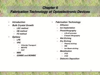
6. Optoelectronic Devices. Optical Waveguides. (a) A buried-in rectangular waveguide, (b) a buried-in rib waveguide, (c) a strip-loaded waveguide, and (d) a diffused waveguide. Some Fabrication Processes of Optical Waveguides. Basic Theory of Waveguides. Theory of Planar Optical Waveguides.

E N D
Optical Waveguides (a) A buried-in rectangular waveguide, (b) a buried-in rib waveguide, (c) a strip-loaded waveguide, and (d) a diffused waveguide
Approximate Theory of Rectangular Optical Waveguides Surrounding by a Uniform Medium
Approximate Theory of Rectangular Optical Waveguides Surrounding by a Uniform Medium (Cont’)
Approximate Theory of Rectangular Optical Waveguides Surrounding by a Uniform Medium (Cont’)
Applications of Y-Branches and Bends of Conventional Optical Waveguides
Band Structures of Photonic Crystals Eg. The band structures of the 2D square-lattice photonic crystal with the lattice constant is a=0.5μm. The radiusof the pillar is Rc=225nm. And the refractive index of the pillar is 3.16227766.
Photonic Crystals Improving LED Efficiency • Incorporating a photonic crystal into an indium-gallium-nitride (InGaN) LED increases both the internal quantum efficiency and the amount of light extracted. The light is produced in the quantum-well (QW) active region.
Photonic Crystals Improving LED Efficiency (Cont’) Far-field emission patterns from a conventional (left) and a photonic-crystal LED (right) are very different. The latter has a strongly-modified emission pattern due to the scattering of waveguided modes out of the LED chip.
Comparison between the Conventional Waveguides and the PCWGs • The conventional optical waveguides are weakly guided. There exist large power losses in the wide-angle bends/branches. However, the same structures made of line-defect photonic crystals give little losses because the lights were trapped by the defects of the photonic crystals. • Most of the conventional optical waveguide devices can be easily modulated by EO effect, AOeffect, and so on. But only a few photonic crystal waveguide devices can be modulated.
Electro-Optic (EO) Effect • The electro-optic (EO) effect is a nonlinear optical effect that results in a refractive index that is a function of the applied electric field (voltage) • Examples of Pockels effect : Ammonium dihydrogen phosphate (ADP), Potassium dihydrogen phosphate (KDP), Lithium Niobate, Lithium Tantalate, etc. • Examples of Kerr effect: Most glasses, gases, and some crystals Pockels effect: Kerr effect:
Phase Modulators • Phase shift = , where Vπ (the half-wave voltage) is the voltage applied to achieve a phase shift of π radians.
Mach-Zehnder Modulator to Modulate Amplitude of Light Output Intensity: Consider the case of φ0=0. If V=Vπ, then Iout=Iin is the maximum, else if V=0, then Iout=0 is the minimum.
Characteristics of Optical Modulators/Switches • Extinction Ratio:η=(I0-Im)/I0 if Im≦I0 and η=(Im-I0)/Imif Im≧I0, where Im is the optical intensity when the maximum signal is applied to the modulator and I0 is the optical intensity with no signal applied. • Insertion Loss:Li=10log(It/Im), where It is the transmitted intensity with no modulator and Im is the transmitted intensity when the maximum signal is applied to the modulator. • Bandwith: △f=2π/T, where T is the switching time.
Coupled-Mode Equations (Cont’) • The coupling length is Lc=π/2κ. Both Lc and κ depend on the refractive index distribution of guide. • While the waveguiding mode traverses a distance of odd multiple of the coupling length (Lc, 3Lc, …, etc), the optical power is completely transferred into the other waveguide. But it is back to the original waveguide after a distance of even multiple of the coupling lengths (2Lc, 4Lc, …, etc). If the waveguiding mode traverses a distance of odd multiple of the half coupling length (Lc/2, 3Lc/2, …, etc), the optical power is equally distributed in the two guides.
Acousto-Optic (AO) Modulators Bragg-type: Width >>2/ Raman-Nath-type: Width <<2/ : wavelength of light : wavelength of acoustic wave Bragg-type AO modulator: sinθB=/2 Raman-Nath type AO modulator: sinθm=m/2, m: integer
Bragg angle: : wavelength of light : wavelength of acoustic wave Bragg-type AO Modulator as Spectrum Analyzer Acousto-optic materials: Visible and NIR — Flint glass, TeO2, fused quartz Infrared — Ge High frequency— LiNbO3, GaP Operations of Bragg-type AO modulator: — Bragg diffraction effect — Driving frequency: 1MHz ~ 1GHz — Rise time: 150 ns (1-mm diameter laser)
Direct Coupling from Laser/Fiber to Waveguide • Direct Coupling Efficiency: where is the laser/fiber mode and is the waveguide mode.
Simulation Results Coupling Efficiency from Laser/Fiber to Waveguide For given waveguide’s fundamental mode, one can obtained the optimal coupling efficiency by selecting the values of w and c.
Band Theory of Semiconductor Devices • Metal: The conduction band and the valence band may overlap. • Semiconductor: The bandgap between the conduction band and the valence band is very small. The electron can be easily excited into the conduction band to become a free electron. • Insulator: The bandgap between the conduction band and the valence band is very large. The electron is hardly excited into the conduction band to become a free electron.
Semiconductor Fermi energy level, EF: the highest energy level which an electron can occupy the valance band at 0°k
Radiation from a Semiconductor Junction wavelength of radiation: where : energy gap (ev) : wavelength of radiation (nm) e.g. GaAs =1.43 ev, find the radiation wavelength