Optoelectronic Integration
05/05/14. Optoelectronic Integration.

Optoelectronic Integration
E N D
Presentation Transcript
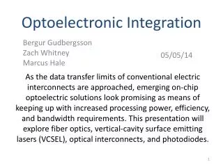
05/05/14 Optoelectronic Integration As the data transfer limits of conventional electric interconnects are approached, emerging on-chip optoelectric solutions look promising as means of keeping up with increased processing power, efficiency, and bandwidth requirements. This presentation will explore fiber optics, vertical-cavity surface emitting lasers (VCSEL), optical interconnects, and photodiodes. Bergur Gudbergsson Zach Whitney Marcus Hale
Outline Fiber Optics • Basics of Fiber • Fiber types • Optical Power • Transmission Bands • Wave Division Mux PIN Photodiode • Absorption • Energy Band Diagrams • Applications VCSEL • Basic Operation • Structure • VCSEL-PIN TRx function & fabrication Optical Interconnects • Basic operation
The Basics of Fiber • A fiber cable consists of: • Core • Cladding • Buffer • Jacket • “Total Internal Reflection”
Claddinghas lower refractive index than the core which causes total internal reflection within the core 4
Fiber Types • Two main types of fiber optics cables • Single Mode Fiber (SMF) (9μM) • Multi Mode Fiber (MMF) (62.5μM or 50μM)
Single Mode Fiber • Small core carries single mode of light • No modal dispersion • Long-haul data transmission • Requires expensive coherent laser light source • Requires specific connector alignment • Operates in 1.3μM -1.5μM Region
Multi Mode Fiber • Multiple modes of light can propagate • Modal dispersion limits distance (500 meters) • Uses cheaper light sources • LED • VCSEL • Larger alignment tolerances • Typically operates at 0.85μM
Optical Power • Light follows “inverse square law” • inversely proportional to distance squared • Attenuation = loss of intensity • Measured in Decibel-milliWatts (dBm/dBmW) • 0dBm is 1 mW • 3dBm is 2 mW • -50dBm is 10 nW
Transmission Bands Split into four windows • 850nM • High attenuation • 1310nM • Zero modal dispersion for SMF • Up to 10kM reach • 1550nM (Conventional-band) • Amplified via erbium doped fibers • 1570-1610nm (Long-band)
Typical Mux/Demux System • Multiple signals are generated • Multiplexer combines the lights into a signal carrier signal • Signal is transmitted • λν=c • Signal is re-separated • Signal is received
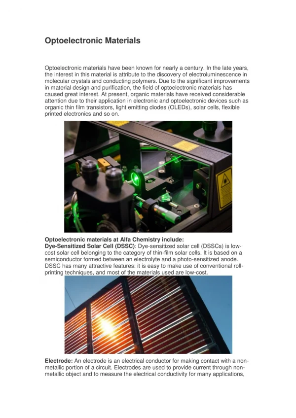
PINPhotodiodes Photodiodes with an Intrinsic (undoped) region between highly doped P and N junctions. Anti-reflection (1/4 wavelength)
Absorption • Photons Absorbed in the intrinsic region • Creates Carriers • Increases Photocurrent (Light into Current) • Si: infrared(700nm) up to 1μm • InGaAS: up to 1.7μm (Longer wavelengths)
Applications • Optical fiber communications • Security Systems • Cameras • Light Controls http://www.hamamatsu.com/cs/Satellite?blobcol=urldata&blobheadername1=content-disposition&blobheadervalue1=inline%3Bfilename%3D149%2F656%2Fk_s1226-44bq_bk_-5bq_bk_pp_xx.jpg&blobkey=id&blobtable=MungoBlobs&blobwhere=1328686465431&ssbinary=true
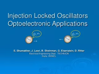
Introduction to VCSELs • Vertical Cavity Surface Emitting Lasers • Different from typical Laser Diodes • Laser is perpendicular to the surface. • P and N doped regions act as parallel DBR mirrors, also forming a diode junction. • Multiple quantum wells • Able to arrange in dense 1 or 2D, on-chip arrays.
History of VCSELs • 1979 first device using GaInAsP/InP • 1988 first continuous wave using GaAs • Today, GaAs-AlGaAs material is favored, 850nm wavelength used for short-haul data communication (monolithic TRx)
VCSELs Basic Structure Typical Laser Diode VCSEL
VCSEL-PIN TRx • Monolithic transceiver chips coupled with MMF • Miniaturization only possible with PIN PD • Why? • Data Rates in the 10-Gb/s range • Arrays allow Optical Interconnects even higher rates
VCSEL-PIN TRx Fabrication • Two stacks of MBE layers • PIN PD grown in the same run of the VCSEL layers. • Order is important
VCSELs PROS CONS Poor thermal characteristics at high-power (980nm+) Increased heat increases threshold current Reduced output at high-power Reduced output at longer wavelengths • Easy testing throughout fabrication • High reflectivity mirrors • Reduced threshold current (down to the 10’s of uA) • Low power consumption
Correcting Thermal Issues in VCSELs • Experiments with various passivation layers • SiO2 (dated) • High resistivity and insulation • Poor heat conductivity (1W/mK) • AlN (new fabrication) • High resistivity • High heat conductivity (300W/mK) • Increased temp distribution, reduces thermal resistance • Carbon Nanotubes (future?)
Final Thoughts on VCSELs • VCSLEs experiencing huge growth as electrical interconnects slowly become obsolete • VCSELs are attractive for short-haul, large data transfers • Can densely back in 1D & 2D array allowing for increased output as well as easy packaging • Great, and basically only choice for optical interconnects
Brief Overview of Optical Interconnects • Advantages • Keep up with Moore’s Law • Higher carrier frequency • Less crosstalk • Lower power consumption • Data ranges in the range of Tb/s • http://www.youtube.com/watch?v=0U4Af2qmgFA (similar but using silicon based lasers)
Conclusion • All of these optoelectrical innovations contribute to the growing field of optical interconnection technology • Immensely complex, research still underway • Huge growth potential
References • Arshad, T. S., Othman, M. A., & Yasin, N. Y. Comparison on IV Characteristics Analysis between Silicon and InGaAs PIN Photodiode.IEEE (ICICI-BME), 71-75. Retrieved May 1, 2014, from http://ieeexplore.ieee.org/stamp/stamp.jsp?tp=&arnumber=6698467 • Introduction to DWDM For Metropolitan Networks. (2000). San Jose, CA: Cisco Systems, Inc. • Kenichi, I. VCSEL -Its Conception, Development, and Future-. IEEE (MOC' 13), 1-2. Retrieved May 1, 2014, from http://ieeexplore.ieee.org/stamp/stamp.jsp?tp=&arnumber=6715057 • Kern, A., Al-Samaneh, A., Wahl, D., & Michalzik, R. Monolithic VCSEL–PIN Photodiode Integration for Bidirectional Optical Data Transmission. IEEE JOURNAL OF SELECTED TOPICS IN QUANTUM ELECTRONICS, 19, 1-13. • Lifeng, H., Yongfeng, M., & Yuan, F. Fabrication and Testing of 980nm High-Power VCSEL with AlN Film Passivation Layer. IEEE (ICOM), 45-48. Retrieved May 1, 2014, from http://ieeexplore.ieee.org/stamp/stamp.jsp?tp=&arnumber=6316212
References • Mishra, S., Chaudhary, N., & Singh, K. Overview of Optical Interconnect Technology. International Journal of Scientific & Engineering Research, 3, 1-7. Retrieved May 1, 2014, from http://arxiv.org/abs/1303.3954 • Muramoto, Y., & Ishibashi, T. InP=InGaAs pin photodiode structure maximising bandwidth and efficiency. ELECTRONICS LETTERS, 29. • Paschotta, D. R. (n.d.). p–i–n Photodiodes. Encyclopedia of Laser Physics and Technology. Retrieved May 1, 2014, from http://www.rp-photonics.com/p_i_n_photodiodes.html • Paschotta, R. (n.d.). Passive Fiber Optics. Tutorial “”: multimode fibers, number of modes, core diameter, numerical aperture, graded-index fiber. Retrieved May 1, 2014, from http://www.rp-photonics.com/passive_fiber_optics4.html • Single mode optical fiber. (2014, April 22). Wikipedia. Retrieved May 2, 2014, from https://en.wikipedia.org/wiki/Single_mode_optical_fiber
References • Steenbergen, R. (Director) (2013, February 4). Everything You Always Wanted to Know About Optical Networking - But Were Afraid to Ask. NANOG57. Lecture conducted from GTT, Orlando, Florida. • Technologies. (n.d.). . . Retrieved May 1, 2014, from http://www.pacer.co.uk/Assets/Pacer/User/Photodiode%20Typical%20Applications.pdf • Total internal reflection. (2014, April 28). Wikipedia. Retrieved May 2, 2014, from https://en.wikipedia.org/wiki/Total_internal_reflection • Zeghbroeck., B. V. (2011, January 1). Chapter 4: p-n Junctions. Optoelectronic devices. Retrieved May 1, 2014, from http://ecee.colorado.edu/~bart/book/book/chapter4/ch4_6.htm • http://en.wikipedia.org/wiki/Vertical-cavity_surface-emitting_laser • http://en.wikipedia.org/wiki/Laser_diode
Key Points • Single Mode fibers are used in long data transmission. Multimode Fibers are cheaper and are used for short distances • Light signal intensity is measured in dBmW • PIN PDs create one electron-hole pair per entering photon. • VCSELs allow for minimal power use and densely packed on chip integration • Monolithic VCSEL-PIN based transceivers allow for short-haul data transfer in the 10Gb/s range.