Download
1 / 11
110 likes | 221 Views
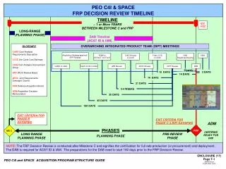
VME64x Digital Acquisition Board (TRIUMF-DAB). Designed to handle 2 channels of 12-bit 40MHz Data Will be used for both the LTI & LHC beam position system and the SPS, LTI and LHC fast beam intensity measurements. DAB History. 1999

E N D
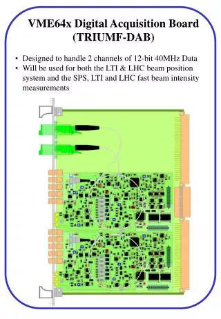
VME64x Digital Acquisition Board (TRIUMF-DAB) • Designed to handle 2 channels of 12-bit 40MHz Data • Will be used for both the LTI & LHC beam position system and the SPS, LTI and LHC fast beam intensity measurements
DAB History • 1999 • Collaboration set-up between CERN and TRIUMF as part of the Canadian contribution to the LHC. • 1 FTE for electronics engineering (Daryl Bishop) • 1 FTE for software engineering (Graham Waters) • 1MCHF for production and testing of all DABs • 2000 • First prototypes produced - standard VME32 card – could process 3 channels simultaneously (HOR, VER and INT) • FPGA - 2 ALTERA FLEX EPF10K30 • WBTN card also a separate module (of VME size) communicating to the DAB via the P2 connector (no optical transmission). • 40MHz Timing produced by on-board PLL • Tested in the SPS (BA4) – still operational today. • Intended for use in the LHC tunnel along with WBTN and front-end processor! • Tested for radiation hardness (TCC2) – as expected had huge SRAM error counts even for moderate radiation + some latch-ups in the FPGA itself.
DAB History • 2001 • WBTN moves to optical transmission. • Separate intensity transmission abandoned. • DAB modified to integrate 2 WBTN mezzanine cards. • FPGA - ALTERA MAX EPM3128 for VME • - ALTERA APEX EP20K200 as main • TTC timing integrated (PLL abandoned). • DAB II prototype successfully tested in the LAB. • Decision taken to use the DAB for FBCT • 2002 • 10 DAB III modules produced – slight modifications wrt DAB II. • DABIII successfully tested with beam (BA5 on 4 PUs) • Near full functionality implemented & tested • Canadian contribution cannot cover 1MCHF for DAB • 2003 • DAB64x specs finalised in January 2003 • Prototype to be ready by July 2003 • FPGA – ALTERA Stratix • TT40 tests will use DAB III (3 cards) • Require ~30 DAB64x cards for mid 2004 • Production and testing will now be done at CERN
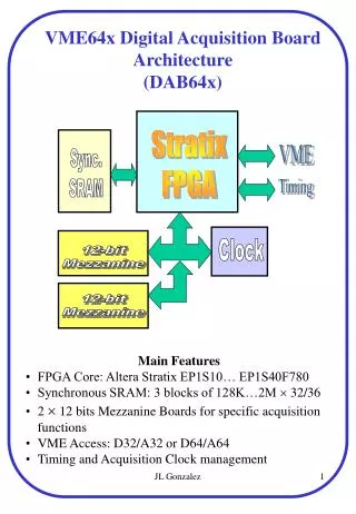
VME interface Code kept in non-volatile memory Workhorse FPGA Code downloaded on each reboot Mezzanine card containing the ADC External memory (3 x 4MB) (128K x 32 Synchronous Flow-Through Cache RAM)
Table 3. APEX 20K Device Overview (2.5 V) Device EP20K100 EP20K200 EP20K400 Maximum System Gates 263,000 526,000 1,052,000 Logic Elements (LEs) 4,160 8,320 16,640 Maximum RAM bits 53,248 106,496 212,992 Phase-Locked Loops (PLLs) 1 1 1 Speed Grade (1) -3, -2, -1 -3, -2, -1 -3, -2, -1 Maximum User I/O Pins 252 382 502 Package(mm) Maximum User I/O Pins 144-Pin TQFP20 x 20 101 208-Pin PQFP28 x 28 159 240-Pin PQFP28 x 28 189 208-Pin RQFP28 x 28 144 240-Pin RQFP28 x 28 174 324-Pin FineLine BGA Package19 x 19 252 356-Pin BGA35 x 35 252 277 484-Pin FineLine BGA Package23 x 23 382 652-Pin BGA45 x 45 502 672-Pin FineLine BGA Package27 x 27 502 Main FPGA - EP20K200 Next version will be an even larger FPGA ALTERA Stratix with more internal memory and some DSP blocks
Modes of Operation • Orbit Mode - Real time acquisition at 10Hz • Sum & Count of all bunches over T turns • LEP experience - default T set to 224 turns (20ms) for 50Hz elimination • Sum & Count of each individual batch over N turns • Sum & Count of 16 individual bunches over N turns • Capture Mode (Triggered on demand) • Acquisition of N bunches for T turns where NT 100000 • i.e. 1 bunch for 100000 turns or 100 bunches for 1000 turns • Sum & Count of all bunches or individual batches for >1000 turns • Post-Mortem (Continuously updated) • Sum & Count of all bunches over 1 turn for 1000 turns • Last 1000 orbit acquisitions • Asynchronous Mode (Calibration Mode) • Allows acquisitions in absence of bunch synchronous clock
Quality Control • Data clocked in by the ADC Strobe • Data either In-Range or Out-of-Range or No-Strobe • Out of range data counted as an error count in orbit and post mortem modes. • Use of ADC strobe to latch in the data gives a wide time range over which data is stable (~15ns out of 25ns). i.e. phase of the 40MHz clock not too critical • Histogram acquired with each orbit • 12-bit histogram of all valid bunches acquired for each orbit. • Gives the spread of the data. • Global bunch mask • Allows the masking of any bunch if for any reason it should not be considered for the orbit acquisition • e.g. pacman bunches or if first bunches in a batch are found to have different electronic offsets. • Look-up table • 12-bit look-up table allows corrections to the data to be applied locally. • e.g. 3rd order correction for a single WBTN channel
Added Features for FBCT • Full 12-bit functionality • LHC BPM system only required 10-bit functionality. • Extra status bit from Mezzannine • Allows the current integrator to be identified • System uses 2 interleaved integrators working at 20MHz to give a 40MHz data stream. • Integrator offset subtraction • Uses this extra status bit to subtract the relevant integrator offset. • Addition of a 13th batch • Allows a measurement of the no-beam FBCT offset on a turn-by-turn basis. • The droop of the FBCT means that this offset changes after each injection and with any intensity changes.
Other Features • Turn clock adjust • Each mezzanine independently adjustable by 3564 25ns slots • 40MHz phase adjust • Each mezzanine independently adjustable in steps of 2ns • LEMO Inputs (TTL Level / 50W) • – Turn Clock • – 40MHz • – capture start • – orbit start • LEMO Outputs (TTL Level / 50W) • 2 outputs for 14 software multiplexed signals • SPS/LHC machine selection switch • JTAG scanbridge interface (next version) • Allows connectivity testing and downloading of code changes
Third injection Second injection Global Orbit Mode (3 PS injections)