Download
1 / 28
300 likes | 355 Views
Learn about the European XFEL project's milestones, funding sources, organizational structure, beam line capabilities, operational flexibility, and future operational modes. Discover the ongoing research and industrialization efforts towards the completion of this cutting-edge facility.

E N D
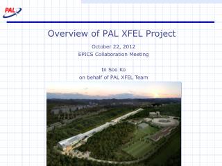
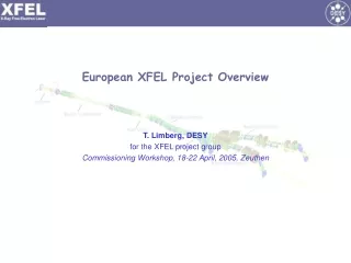
European XFEL Project Overview T. Limberg, DESY for the XFEL project group Commissioning Workshop, 18-22 April, 2005, Zeuthen
Project approval status and time line • Proposal October 2002: X-ray FEL user facility with 20 GeV superconducting linear accelerator in technology • Approval by German government Feb. 2003 as a European Project • German commitment for 50% of the funding plus another expected 10% by the states Hamburg and Schleswig-Holstein, 40% from European partners • Estimated total project cost 908M€, including preceding R&D and escalation over 2006 – 2012 construction period
Ongoing Project Organisation at European Level • XFEL Steering Committee (Chair: H. Schunck, BMBF) • Representatives of all countries intending to contribute to the XFEL facility • 10 countries have signed MoU for project preparation phase (CH,DE,DK,ES,FR,GR,IT,PL,SE,UK) • WG on Scientific and Technical issues STI (chair: F. Sette, ESRF) • Reach consensus on the scientific goals and the overall layout of the facility • WG on Administrative and Funding issuesAFI (chair: H.F. Wagner, BMBF) • Work out legal framework and organizational scheme for construction & operation • Explore and reach consensus on the cost breakdown and spending profile STI interim report Jan. 2005
Site near DESY laboratory 3.2km Possible extension 1st stage
Site Planning / Construction Permission • Staatsvertrag between Länder Hamburg and Schleswig-Holstein in effect since Jan. 2005 • Preparations for Plan Approval Procedure ( permission of construction & operation of the facility) almost completed • Official start of the procedure in a few weeks from now, aim at successful completion before end 2005
User facility - Beam lines I • SASE undulators 0.1 – 6nm, magn. Length 150 – 80m • Variable gap (min 10mm) independent -tuning, electron/photon beam alignment • Options: fast independent switch of FEL process for sequence of U’s, sub-fs pulses by modulation with ultra-short laser, seeding, …
Operational flexibility – time structure • S.c. linac can accelerate large number (> 3,000) of electron bunches per RF pulse variable time structure of bunch trains for different user requirements
Beam distribution and civil construction layout includes: • Fast kicker concept • Accessibility of undulator beam line while others are in operation • Connection to a an extension of the user facility in a 2nd phase of the project
MAD Survey Output Plot SASE 3 SASE 1 Undulator 1 SASE 2 SASE 4
“Campus” near Schenefeld Phase II
Infrastructure/sub-systems (water cooling, cryo plant, modulator hall, injector, …) on DESY site Linac Injector
Schematic Layout of Accelerator 1st Chicane at 0.5 GeV 2nd Chicane at 2.5 GeV 1.7 km 0.4 km (120 Modules, 30 RF stations)
Wavelength vs. Accelerator Gradient Nominal linac energy 20 GeV, includes 57Fe line @ 0.8Å Expected better cavity performance permits higher energy/smaller wavelength
Operational Flexibility – Duty Cycle T_beam [ms] Decreasing Tbeam at higher frep helps, but injector is an issue!
Sketch of possible future CW operation mode If Å FEL radiation at lower beam energy comes in reach (better injector/beam quality, advanced FEL concepts, …) high duty cycle, up to CW, can become an attractive option Linac layout & cryogenics are consistent with this option (at Eacc = 7…8 MV/m), a different RF system has to be added Maintain good RF beam efficiency with moderate over-coupling (87 Hz bandwidth, expect <10 Hz rms microphonics)
Sketch of future CW operation mode cont’d If user demand for very high average power, ERL option is conceivable
5 MW RF source var. Q_ext with adjustable coupler and/or waveguide tuner De-rated 10MW MBK Bouncer-type modulator 12m TTF-like acc. modules eight 9-cell Nb cavities at 2K, Q0=1010
Ongoing R&D programme / industrialization(examples, not exhaustive) • Qualification of additional vendors for 10MW multi-beam klystrons • Launch studies for klystrons/pulse transformers suitable for tunnel installation • Test with 1.5km 10kV pulse cable successful; need more studies of EM noise issues • Industrial studies for production of 1,000 RF power couplers (procurement LAL/Orsay) • Gain more experience with s.c. cavity treatment: procedure includes electro-polishing, no 1400C/titanisation (only 800C) • Improve throughput at TTF infrastructure with 2nd high pressure rinsing facility • Try out P. Kneisels (JLAB) method to fabricate cavities directly from Nb ingot • Industrial studies for accelerator module assembly • Module teststand under construction (completion ~end 2005) • Development of “cold” BPMs (collab. Saclay) • Development of cavity tuners incl. piezo (collab. Saclay, INFN-Milano) • Development of s.c. magnets (collab. CIEMAT)
Cavity Production Status • Ongoing R&D program: • Gain more experience with s.c. cavity treatment: procedure includes electro-polishing, no 1400C/titanisation (only 800C)
Injector & 1st Chicane of Bunch Compressor 100 MeV 500 MeV 1st Bunch Compressor Chicane Main Linac >100 Modules Injector I 3rd Harmonic Booster Injector II XTL XSIN XSE 0 m 50 m 80 m ca. 150 m ca. 270 m • Beam quality from injector + B.C. sub-systems is decisive for the FEL performance • Extensive beam dynamics & parameter studies Invaluable input from TTF/VUVFEL experience!
Emittance from photocathode RF gun injector • 1nC charge • uniform transverse distribution • longitudinal flat-top with2 ps rise time • incl. thermal emittance
RF gun development at PITZ, DESY-Zeuthen • On-going programme: • increase the gradient on the cathode from 40 MV/m to 60 MV/m • further improve the transverse and longitudinal laser profile (collab. Max-Born Institute, Berlin) • PITZ gun now part of TTF-II/VUVFEL injector 1.7
Recently improved BC concept: 2-stage system Reduced space charge effects, more flexibility in bunch parameter space
design value at undulators Flexibility in Peak Current • Note: • effect on projected emittance is larger • stabilization & timing issues are challenging (e.g. RF phase stability ~0.01 !)
Conclusions • The 20 GeV s.c. linac based on the technology developed by the TESLA collaboration and successfully demonstrated at TTF is an ideal driver for the Free Electron Laser facility, offering a broad range of operating parameters in its baseline design and with future upgrade options. • With the R&D work towards industrial production of major components, the preparations for the site at DESY and the European project organisation under way, we should be ready to go into construction phase in 2006.