Recent Results: Thermal Conductivity
20 likes | 154 Views
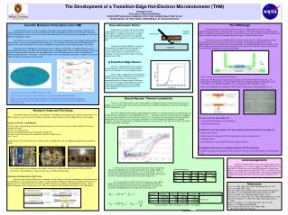
Incoming radiation. Thermometer. Absorber. Weak Link. Cold Bath. Mo Leads. 10um. Mo/Cu TES. 38um. Bi Absorber. The Development of a Transition-Edge Hot-Electron Microbolometer (THM) Emily Barrentine University of Wisconsin-Madison

Recent Results: Thermal Conductivity
E N D
Presentation Transcript
Incoming radiation Thermometer Absorber Weak Link Cold Bath Mo Leads 10um Mo/Cu TES 38um Bi Absorber The Development of a Transition-Edge Hot-Electron Microbolometer (THM) Emily Barrentine University of Wisconsin-Madison NASA-GSRP Symposium, September 20-22, 2006, Goddard Space Flight Center Faculty Advisor: Dr. Peter Timbie, NASA Advisor: Dr. Thomas Stevenson Scientific Motivation: Polarization in the CMB In the hot and dense early universe, electrons and photons were rapidly colliding via Compton scattering. The universe expanded and cooled, however, and 379,000 years after the Big Bang, the electrons “recombined” with atomic nuclei and the photons were free to travel, for the most part undeflected. These photons are observed today as the Cosmic Microwave Background (CMB). The CMB tells us about the conditions of the universe at the time of recombination, and indirectly, about conditions during inflation, an era of very rapid expansion during the first ~10-34 seconds. Observations of the CMB can also tell us about the later structure formation in the universe, and provide insight into dark matter and dark energy (TFCR 2005). Polarization of the CMB light can form different patterns called E- and B-modes. E-mode polarization was first measured by DASI (Kovac et al. 2002), but the B-Mode signal is expected to be at least an order of magnitude smaller and has not yet been detected. A detection of B-mode polarization in the CMB would confirm one of the key predictions of inflation, gravitational waves (TFCR 2005) . To detect B-modes more sensitive detector technology is needed and an array of 1000’s of THMs would be able to fulfill this need. How a Bolometer Works: A bolometer is a detector that directly absorbs incident photon energy in the form of heat. It consists of three parts: an absorber, thermometer, and cold bath. Incoming photons thermalize in the absorber, and heat leaves the absorber via a weak link to a cold bath. The power of incident radiation is measured by monitoring the temperature of the absorber. To measure small differences in incident power a sensitive thermometer is needed. We will use an extremely sensitive thermometer called a Transition-Edge Sensor, or TES. A Transition Edge Sensor: A TES is a superconductor which exhibits a transition between a normal and superconducting state. At this transition its resistance drops to zero. When a TES is voltage-biased, electrothermal feedback (Irwin & Hilton, 2005) causes it to remain in the transition region where a small change in temperature results in a large change in resistance, and current. This temperature-proportional current is read out by a compatible and low noise amplifier called a Superconducting Quantum Interference Device (SQUID). • The THM Design • The THM design (Ali et al. 2003, similar to Karasik et al. 2003)consists of a small volume superconducting thin Mo/Cu (or Mo/Au) bilayer film that acts as a TES, with a separate normal Bi film which acts as an absorber. By adjusting the thickness ratio of Mo/Cu we can adjust the TES transition temperature to match the optimal temperature for ground (300mK) and space (100mK) based missions. • These devices are easily integrated with microstrip transmission lines and planar antennas. A Nb microstrip line terminates at the absorber where the energy is absorbed by the quasiparticles in the superconducting film. At low temperatures the quasiparticles are strongly decoupled from the phonons in the TES and bath, and will remain at a higher temperature. We expect this “hot-electron” effect to dominate the thermal conductivity between the device and heat bath. • The small size of the device allows for: • Dense packing of bolometers in the focal plane • Limited Cosmic Ray noise • In addition, the small size provides a low heat capacity and thermal conductivity that allows for: • High energy resolution • Short time constant between the TES and heat bath for rapid scanning of the sky • Low phonon noise • Easy fabrication (no micro-machined thermal isolation structures) • The separation of the device into a separate absorber and TES will allow for: • Separate impedance matching to the microstrip transmission lines and SQUID readouts, minimizing signal • loss Temperature Temperature/E-mode Correlation Above: The layout for one prototype THM device. Below right: The design when coupled to a microstrip, and the thermal model. We expect Gep, the electron-phonon conductivity << GWF the Weidemann-Franz conductivity between the electrons in the TES, and Gep>> the Andreev conductivity, GAndreev between the TES and higher Tc leads. Below left: Photograph of two prototype THMs (courtesy Robin Cantor, StarCryoelectronics, LLC.). E-Mode B-Mode The most recent results from WMAP (Page et al. 2006): Left: A map of the Ka-Band Q-Stokes Parameter, a measure of polarization in the CMB. Right: The power spectrum of the CMB Temperature, Temperature/E-mode Polarization and E-Mode Polarization signals. An array of THMs would have the sensitivity to reach the predicted B-Mode signal level shown in blue. Recent Results: Thermal Conductivity The first run of THM test devices were made of Mo/Au at Goddard and were tested at University Wisconsin-Madison (Ali et al. 2003, 2004).We are presently testing some new Mo/Cu THM devices, which were fabricated at STARCryoelectronics, LLC. One of the important steps towards understanding these devices is to determine the thermal conductivity and its dependence on temperature. In the graph below the R vs. T transition curve for one THM test device is mapped out using a lock-in amplifier to send a small AC current (0.1uA) through the TES and monitoring the corresponding voltage drop. A DC current is then sent through the absorber. As the Joule power dissipated in the absorber increases, a temperature differential is established between the “hot” electrons in the TES and the bath, which shifts the bath temperature at transition. • Research Goals and Test Setup • The long-term goal of this project is to incorporate a THM detector into a polarimeter to observe polarization in the CMB. However, we must first test and improve our design in order to demonstrate the applicability of this technology. • Testing “in the dark” at UW-Madison: • The first step in understanding and demonstrating these devises is to test them without incident radiation. These tests include measuring: • the R vs. T transition curve • the thermal conductivity between the absorber and the TES • the noise level of the devices with and without a SQUID readout system • the I-V curve • To do these tests we cool the devices to ~200mK using a shielded dewar with an adiabatic demagnetization refrigerator (ADR). • Fabrication at Goddard Space Flight Center: • After the initial testing of THM devices is complete, we will improve our design and fabricate the next generation of test THM devices. I will be fabricating these devices at the Detector Development Laboratory at NASA-GSFC under the guidance of Dr. Thomas Stevenson. The facilities at GSFC allow for many options in the fabrication process, such as optical lithography and dry etching (Allen et al. 2003). An example of the THM fabrication process is illustrated below: Acknowledgements The Mo/Cu THM test devices were fabricated by Robin Cantor at StarCryoelectronics LLC. with the support of a NASA-SBIR grant. The initial Mo/Au THM devices were tested by Shafinaz Ali at University of Wisconsin and fabricated at the NASA-GSFC DDL. The SQUID used to read out these THMs was provided by NIST. I was partially supported by the Wisconsin Space Grant Consortium during the completion of this work. SQUID THM In these tests, at Tc, the power transferred into the bath should follow a power law dependence on the bath temperature (Irwin & Hilton, 2005). In the case of the electron-phonon effect Pbath~Tbath5 and G~dP/dT ~Tbath4. An estimate for the thermal conductivity of the device can be made by measuring the shift in the bath temperature from the transition temperature. Our G estimate for the Mo/Cu StarCryo test devices is only slightly higher then is predicted from literature values (see table below). We are presently working to determine the power-law dependence, as well as the reason for the broadening of the transition with increased current. On the left the dewar, with shielding, in the middle, a look at the inside of the dewar, where the THM and SQUID will reside in a Nb shielded can, and on the right, the test THM and SQUID chips. Device Dimensions: References Ali, S. et al. 2003. IEEE Trans. Appl. Superconductivity, 13, 184. Ali, S. et al. 2004, SPIE, 5498. Allen et al. 2003, Proc. 10th Workshop of Low Temperature Detectors. Dorozhkin, S.I. et al. 1986 Solid State Communications, 60, 245. Irwin, K.D, Hilton, G.C. 2005, Topics Appl. Physics, 99, 63. Karasik, B.S. et al. 2003, IEEE Trans. Appl. Superconductivity, 13, 188. Nahum, M., Richards, P.L. IEEE Trans. Appl. Superconductivity, 27, 2484. Nahum, M.& Martinis, J.M., 1993, Appl. Phys. Lett., 63, 3075. Page, L. et al. 2006, astro-ph/0603450 Task Force on CMB Research, Final Report, 2005, http://www.nsf.gov/mps/ast/tfcr.jsp. *(Nahum & Martinas, 1993),**(Dorozhkin et al. 1986) *** At T=300mK