Download
1 / 25
250 likes | 343 Views
The Mw 6.3 Movri Mountain earthquake, June 8, 2008, Greece. Sokos E. 1 , Serpetsidaki A. 1 , Tselentis G. 1 , Gallovic F. 2 , Krizova D. 2 , Plicka V. 2 , Zahradnik J. 2. 1 Department of Geology, Seismological Laboratory, University of Patras, Greece

E N D
The Mw 6.3 Movri Mountain earthquake, June 8, 2008, Greece Sokos E.1, Serpetsidaki A. 1, Tselentis G. 1, Gallovic F. 2, Krizova D. 2, Plicka V. 2, Zahradnik J. 2 1Department of Geology, Seismological Laboratory, University of Patras, Greece 2 Charles University in Prague, Czech Republic
The M6 event of the 2008 ‘storm’ of strong earthquakes in Greece Papadopoulos, G. A., V. Karastathis, M. Charalambakis, A. Fokaefs (2009). A Storm of Strong Earthquakes in Greece During 2008, Eos Trans. AGU, 90, 425–426.
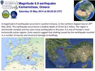
DAMAGING EFFECTS • Significant event • Extensive damage • Two victims • Hundreds of injuries ITSAK: http://www.itsak.gr/news/categories/24
REGIONAL FRAMEWORK Strike slip Depth ~ 20km Relatively rare event of this size (Mw 6.3) in NW Peloponnese CMT - http://www.globalcmt.org/CMTsearch.html
Geology - tectonics • Μain geological formationsare flysch and limestone; parts of Pindos and Gavrovo isopic zones • The main tectonic feature is the ~NS trending Scolis thrust Koukouvelas et al., 2009, IGR
INITIAL LOCATION • Epicenter located between villages Dafni and Michoi • The activated zone clearly proves the SW-NE fault plane • Similar results obtained by Ganas, et.al 2009, JEE. • No clear relation of fault plane to mapped surface faults (blind event, depth ~20 km) • (Red lines are co-seismic ruptures, Koukouvelas et al., 2009, IGR)
RELOCATION OF THE SEQUENCE (HYPODD) FIRST DAY SEISMICITY SW NE
RELOCATION OF THE SEQUENCE (HYPODD) Two clusters North: M < 4.4 ~30 events M3 within 13 hours after mainshock
RELOCATION OF THE SEQUENCE (HYPODD) Two clusters North: M < 4.4 ~30 events M3 within 13 hours after mainshock South: M < 3.3 first M>3 only 13 hours after mainshock
SOURCE INVESTIGATION (MAINSHOCK) Near-regional stations Frequency < 0.2 Hz PSLNET BB and SM (SER, MAM, LTK, PYL co-operated by Charles Univ.) ITSAK SM NOA BB
CENTROID AND HYPOCENTER Centroid position as a part of the CMT solution (ISOLA software; Sokos and Zahradnik, 2008) C at about 8 km from H toward NE Indication of the rupture propagation toward NE C H
ISOLA codemodified to prevent a highly concentrated slip (Zahradnik et al., JGR, in press) a new technique (Gallovic et al., GRL 36, L21310, 2009), iterative back-propagation of the waveform residuals by the conjugate gradients technique SLIP INVERSION: TWO METHODS The two methods do not need prior knowledge of the nucleation point and rupture velocity.
TWO METHODS – SIMILAR RESULTS Color: the new iterative back-propagation method Green circles: ISOLA modified for distributed slip
TWO METHODS – SIMILAR RESULTS Color: the new iterative back-propagation method Green circles: ISOLA modified for distributed slip Caution: Time versus Distance (a 1D model, not 2D)
TWO METHODS – SIMILAR RESULTS Predominant unilateral rupture propagation along strike (toward NE) Two-three main patches, mutually delayed by almost 5 seconds Delay of the first patch with respect to origin time (inversion assuming Vr=const from H would fail !) H Possible temporary rupture arrest.
Examples of slip models equally well matching real waveforms (variance reduction 0.7) CAUTION ! The result is inherently non-unique. Black circles: an (assumed) patch used to initialize the inversion. More details in oral presentation by Zahradnik and Gallovic (session ES5, Thursday morning)
LINE SOURCE MODEL AND ITS RELATION TO AFTERSHOCKS Recall the two aftershock clusters.
LINE SOURCE MODEL AND ITS RELATION TO AFTERSHOCKS Recall the two aftershock clusters. Main slip released between the two clusters.
LINE SOURCE MODEL AND ITS RELATION TO AFTERSHOCKS Recall also different properties of the two clusters – related to the predominant rupture propagation toward NE
CONCLUSIONS Accurate relocation, combined with the near-regional, low-frequency slip inversion explained rough history of the mainshock and the sequence.
CONCLUSIONS Accurate relocation, combined with the near-regional, low-frequency slip inversion explained rough history of the mainshock and the sequence. Relatively large depth (~20 km) hampered resolution of the slip along fault dip (other authors published the 2D slip, e.g. . Konstantinou et al., BSSA 2009). Line-source model (along strike) proved sufficient to recognize main features of the rupture propagation.
CONCLUSIONS Accurate relocation, combined with the near-regional, low-frequency slip inversion explained rough history of the mainshock and the sequence. Relatively large depth (~20 km) hampered resolution of the slip along fault dip (other authors published the 2D slip, e.g. . Konstantinou et al., BSSA 2009). Line-source model (along strike) proved sufficient to recognize main features of the rupture propagation. The earthquake led to development of two inversion methods, independent of the prior knowledge of the nucleation point and rupture velocity. The source model indicated a few patches with mutual delays; they might have important implication for strong ground motions (a special study needed).
CONCLUSIONS Accurate relocation, combined with the near-regional, low-frequency slip inversion explained rough history of the mainshock and the sequence. Relatively large depth (~20 km) hampered resolution of the slip along fault dip (other authors published the 2D slip, e.g. . Konstantinou et al., BSSA 2009). Line-source model (along strike) proved sufficient to recognize main features of the rupture propagation. The earthquake led to development of two inversion methods, independent of the prior knowledge of the nucleation point and rupture velocity. The source model indicated a few patches with mutual delays; they might have important implication for strong ground motions (a special study needed). Importance of the NE source directivity for hazard assessment of Patras.