Download
1 / 19
190 likes | 312 Views
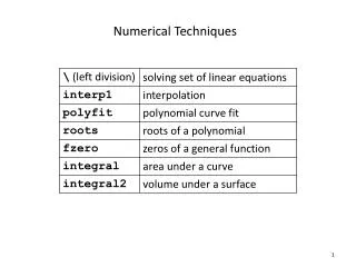
Some numerical techniques developed in the Heavy-Ion Fusion program. J.-L. Vay - Lawrence Berkeley National Laboratory Collaborators: A. Friedman , D.P. Grote - Lawrence Livermore National Laboratory J.-C. Adam, A. Héron - CPHT, Ecole Polytechnique, France

E N D
Some numerical techniques developed in the Heavy-Ion Fusion program J.-L. Vay - Lawrence Berkeley National Laboratory Collaborators: • A. Friedman, D.P. Grote - Lawrence Livermore National Laboratory • J.-C. Adam, A. Héron - CPHT, Ecole Polytechnique, France • P. Colella, P. McCorquodale, D. Serafini - Lawrence Berkeley National Laboratory • The Heavy-Ion Fusion program has developed, and continues to work on, numerical techniques that have broad applicability: • Absorbing Boundary Conditions (ABC) • Adaptive Mesh Refinement (AMR) for Particle-In-Cell (PIC) • Advanced Vlasov methods (moving grid,AMR) • Cut-cell boundaries Short-Pulse Laser Matter Computational Workshop Pleasanton, California - August 25-27, 2004
If and with u=(x,y), Z=Z0 => no reflection. If with u=(x,y), Z=Z0 => no reflection. Extended Perfectly Matched Layer • Principles of PML • field vanishes in layer surrounding domain, • layer medium impedance Z matches vacuum’s Z0. Split Maxwell => Berenger PML Berenger PML => Extended PML Maxwell => Split Maxwell Maxwell
Extended PML implemented in EM PIC code Emi2d Extended PML
3D AMR simulation of an explosion (microseconds after ignition) AMR concentrates the resolution around the edge which contains the most interesting scientific features. The Adaptive-Mesh-Refinement (AMR) method • addresses the issue of wide range of space scales • well established method in fluid calculations • potential issues with PIC at interface • spurious self-force on macro-particles • violation of Gauss’ Law • spurious reflection of short wavelengths with amplification
3D WARP simulation of High-Current Experiment (HCX) Modeling of source is critical since it determines initial shape of beam WARP simulations show that a fairly high resolution is needed to reach convergence
R (m) zoom Z (m) Z (m) Z (m) Refinement of gradients: emitting area, beam edge and front. Example of AMR calculation with WARPrz: speedup ~10.5 R (m)
MR patch Current history (Z=0.62m) Current history (Z=0.62m) MR off MR on MR patch key in simulation of STS500 Experiment • Mesh Refinement essential to recover experimental results • Ratio of smaller mesh to main grid mesh ~ 1/1000
Patch 2s=28/k0 fine F Extended PML core C Laser beam Outside patch: F = FM coarse Inside patch: F = FM-FC+FF coarse M Mesh refinement by substitution 10nc, 10keV l=1mm, 1020W.cm-2 (Posc/mec~8,83) Applied to Laser-plasma interaction in the context of fast ignition New MR method implemented in EM PIC code Emi2d
same results except for small residual incident laser outside region of interest • no instability nor spurious wave reflection observed at patch border Comparison patch on/off very encouraging MR off MR on
Goal: end-to-end modeling of a Heavy Ion Fusion driver challenging because length scales span a wide range: mm to km(s)
In driver -12 -11 -10 -9 -8 -7 -6 -5 -4 -3 -2 -1 0 In chamber Time and length scales in driver and chamber span a wide range Time scales: depressed betatron betatron t electron drift pb out of magnet » transit lattice thru electron period fringe beam cyclotron pulse fields residence in magnet log of timescale pulse beam t pe in seconds residence t pi t pb Length scales: • electron gyroradius in magnet ~10 mm • lD,beam ~ 1 mm • beam radius ~ cm • machine length ~ km's
Illustration of instability in 1-D EM tests o: E, x:B Space only Space+Time Most schemes relying on interpolations are potentially unstable.
3D WARP simulation of HCX shows beam head scrapping Rise-time t = 800 ns beam head particle loss < 0.1% x (m) z (m) Rise-time t = 400 ns zero beam head particle loss x (m) • Simulations show: head cleaner with shorter rise-time • Question: what is the optimal rise-time? z (m)
di virtual surface current time Vi irregular patch in di + AMR following front “L-T” waveform N = 160 Dt = 1ns d = 0.4m AMR ratio = 16 I (A) Time (s) Time (s) 1D time-dependent modeling of ion diode Emitter Collector d V V=0 irregular patch in di Ns = 200 dx0/Dx~10-5! Insufficient resolution of beam front => AMR patch Careful analysis shows that di too large by >104 => irregular patch Time (s) MR patch suppresses long wavelength oscillation Adaptive MR patch suppresses front peak
STS500 experiment X (m) Z (m) Application to three dimensions • Specialized 1-D patch implemented in 3-D injection routine (2-D array) • Extension Lampel-Tiefenback technique to 3-D implemented in WARP • predicts a voltage waveform which extracts a nearly flat current at emitter • Run with MR predicts very sharp risetime (not square due to erosion) • Without MR, WARP predicts overshoot “Optimized” Voltage Current at Z=0.62m V (kV) T (ms)
Effort to develop AMR library for PIC at LBNL • Researchers from AFRD (PIC) and ANAG (AMR-Phil Colella’s group) collaborate to provide a library of tools that will give AMR capability to existing PIC codes (on serial and parallel computers) • The base is the existing ANAG’s AMR library Chombo • The way it works • WARP is test PIC code but library will be usable by any PIC code
Example of WARP-Chombo injector field calculation • Chombo can handle very complex grid hierarchy
Maxwell Extended PML Split Maxwell Berenger PML If and => Z=Z0: no reflection. If with u=(x,y) => Z=Z0: no reflection. Extended Perfectly Matched Layer Principle of PML: Field vanishes in layer surrounding domain. Layer medium impedance Z matches vacuum’s Z0