Download

1 / 35
350 likes | 372 Views
Explore vorticity evolution and losses due to secondary flow vortices in turbines. Understand the impact of secondary flows on main flow distortion and loss mechanisms in turbines.

E N D
Evolution of vorticity from the endwall boundary layer P M V Subbarao Professor Mechanical Engineering Department Methods to Estimate Enhanced Losses along the Flow Path……
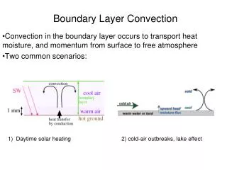
Secondary whirl Need for Description of Secondary Flow as An Elephant !?!?! The main type of secondary flow is the induced recirculating flow, which leads to the formation of a passage vortex.
Classification of Vortices in Edge BL Flow TEV: Trailing Edge vortex. HS: Suction side leg of Horse-shoe vortex. HP: Pressure side leg of Horse-shoe vortex. PV: Passage vortex. CV: Corner vortex.
The Primary Cause : Think like H A Einstein • The important cause of secondary flows is formation of horse-shoe vortex. • The boundary layer fluid upstream of the leading edge is decelerated by the adverse pressure gradient and separates at a saddle point S1. • The boundary layer fluid elements form a reverse recirculating flow just before the leading edge.
Twin Legged HS Vortex • This reverse flow separates at another saddle point S2.. • The upstream boundary layer rolled-up in the recirculating zone flows past the leading edge and is transported downstream in two legs – pressure-side and suction-side leg of the horse-shoe vortex.
The Independent Movements of HSVs • The suction-side leg of the horse-shoe vortex moves near the suction surface of the blade. • The pressure-side leg subject to the pressure gradient towards the suction surface moves across the blade-to-blade passage towards this surface.
Confluence of Vortices • All main forms of secondary flows meet at the suction surface of the blade. • The model that explains the transport of the horse-shoe vortex is more useful for estimation of losses. • The pressure-side leg of the horse-shoe vortex together with the endwall cross flow form the main recirculating flow. • This creates birth to passage vortex, stays apart from the counter-rotating vortex.
Level -1 Infection Due to Secondary Flow Vortices Healthy Stream Lines Infected Stream Lines
Level -2 Infection Due to Secondary Flow Vortices % TL • The core of vortices are regions of a high turbulence level. • The turbulence level at the exit section of the cascade in the passage vortex and trailing shed vortex estimated at 35% with respect to the inlet velocity. • The turbulence level in the suction-side corner vortex is nearly as high as above. • The increase of turbulent fluctuations in the region of secondary vortices can be attributed to the process of deformation of the endwall boundary layer. • This depends on conditions of high streamline curvature and acceleration of the main flow in the cascade. • Namely change in flow deflection angle & Degree of Reaction.
Division of the endwall boundary layer : Region of laminar flow The EWBL is laminar in the major part (downstream of the horse shoe vortex ).
Division of the endwall boundary layer : Region of intermittent flow The EWBL is also seen intermittent at few locations
Division of the endwall boundary layer : Region of laminar,intermittent and turbulent flow EWBL is turbulent only in the rear part of the blade-to-blade passage at the suction surface.
Occurrence of unreasonable Intermittent Flows • The vortex flows wash away the endwall boundary layer towards the suction surface. • This gives rise to relaminarisation of the downstream endwall boundary layer. • The newly formed endwall boundary layer becomes thin. • This will gradually increase in thickness but is constantly washed away. • As a consquence, the endwall boundary layer has a highly three-dimensional transient character. • Serious pressure pulsations are generated in the endwall boundary layer
Endwall loss sources • Production of endwall losses is a complex problem. • Among basic loss mechanisms in the endwall are: • Formation of the inlet boundary layer upstream of the blade leading edge, • Formation of the horse-shoe vortex lift-off lines. • Shear effects along the horse-shoe vortex lift-off lines, separation lines and along dividing surfaces between the passage vortex, other vortices, main flow and blade surfaces, especially at the suction surface. • Dissipation of the passage vortex, trailing shed vortex, corner vortices and other vortex flows in the process of their mixing with the main flow. • It can be assumed that the secondary kinetic energy of the relative motion in the exit section is lost during mixing.
Methods to predict Losses due to SFVs • Secondary flows although undesirable, dominate the flow field in turbines consisting a major source of loss in axial turbines • This aspect is formulated as a differential equation. • The influence of SFVs on Main flow distortion cane be estimated using this differential equation. • This analysis starts with the fact that SFVs of known strength are created at Endwalls.
Evolution of vorticity from the endwall boundary layer • The vorticity transport equation for a steady flow of a viscous compressible gas can be written as below Lakshminarayana and Horlock presented a solution to this equation, which is of interest in turbomachinery applications the first right-hand-side term represents the vorticity production due to the velocity gradient (stretching and curving of vortex lines). second term – describes the vorticity production in compressible flow (reduction in an expanding flow, increase in a compression region), third term – accounts for the baroclinic effect (in the field of spatial changes of pressure and density), fourth term –due to interaction of viscous forces in a compressible flow.
Local Relative Coordinate System • Lakshminarayana and Horlock assumed a coordinate system (s,n, b). • s is the unit vector tangent to the streamline u = sq, (q – velocity magnitude), • n is the unit normal vector directed towards the streamline curvature centre n/R = s.∇s, (R – streamline curvature radius), • b is the unit binormal vector b = s × n, so that (s,n, b) is a right- handed set of vectors.
Lakshminarayana’s Secondary Flow Equations in Turbo-machine Co-ordinate System Simplified differential equations for the evolution of streamwise (s) and normal (n)component of the vorticity vector in the cascade are : In practical applications the streamwise vorticity seems to be of the main significance
Simple case of an inviscid incompressible flow • The principal mathematical description of secondary flows draws on the spatial evolution of the vorticity vector in the cascade. • This description enables better understanding of the phenomena associated with the secondary flows. • In the most simple case of an inviscid incompressible flow Integration along streamlines yields the difference (− 0 ) denotes the current flow turning in the cascade.
Evaluation of Normal Voriticity • In a steady inviscid flow, streamlines and vorticity lines lie on surfaces of constant total pressure (Bernoulli surfaces). • The normal vorticity can be obtained as: denotes the or direction of ∇ptotal.
Quantitative Description of End Wall flow • Based on the known distribution of the streamwise vorticity in the exit section, the exit velocity of the induced flow and the secondary kinetic energy can be evaluated. • Assuming that this energy is lost in the process of mixing with the main flow, one can estimate the level of mixing losses. • The velocity induced at the trailing edge section can be numerically calculated from the Poisson equation for the stream function The components of the induced secondary velocity vr1, vn1 are then found as
Coefficient of Total Pressure Loss Local pressure loss coefficient
Spanwise Profile of curcumferential integrated Pressure loss coefficient