Download
1 / 45
450 likes | 648 Views
chapter 8 Gas Power Cycle . 8-1 The Analysis of a Cycle. T. T. 2. 1. s. s 1. s 2. 8-1-1 The average temperature of a process. We define:. That is:. As to a cycle:. T. a. 2. T 2. 1. b. T 1. s. s 1. s 2. 8-1-2 The Analysis of a Cycle. 8-2 Otto Cycle.

E N D
8-1The Analysis of a Cycle T T 2 1 s s1 s2 8-1-1 The average temperature of a process We define: That is:
As to a cycle: T a 2 T2 1 b T1 s s1 s2 8-1-2 The Analysis of a Cycle
8-2Otto Cycle Nicolaus August Otto the inventor of the four-stroke cycle was born on 14th June 1831 in Germany. In 1862 he began first experiments with four-strokes engines. The first four-stroke engines is shown. they correspond to the today's engines. He died on 26th January 1891 in Cologne 8-2-1 N. A. Otto
8-2-2 The Cycle - The Four Strokes Intake stroke: The piston moves down the cylinder and the pressure will drop (negative pressure). The intake valve is opend. Because of the low pressure the air/fuel mixtures is sucked into the cylinder.
Compression stroke: At Bottom Dead Center (BDC) the cylinder is at its maximum volume and the intake valve is closed. Now the piston moves backward the Top Dead Center (TDC) and compresses the air/fuel mixtures.
Near the end of the compression stroke, the ignition starts the combustion and the mixture burns very rapidly. The expanding gas creates a high pressures against the top of the piston.
Power stroke The force drives the piston downward to crank shaft (the valves are closed). The volume is increased and the pressure is decreased. No more energy is added and because of this the internal energy of the gas is decreased as so as the temperature.
Exhaust stroke At BDC the exhaust valve is opened and the piston moves up the cylinder. The pressure drops near the pressure outside the cylinder because of the opened exhaust valve. Exhaust gas leaves the cylinder. The volume is decreased.
p 3 Adiabatic process 2 4 5 1 v 8-2-3 The Cycle - The Four Strokes The theory cycle
Then: Theory efficiency of Otto cycle
8-3 Diesel Cycle Rudolf Diesel (1858 – 1913) was born in Paris in 1858. After graduation he was employed as a refrigerator engineer. However, his true love was in engine design. In 1893, he published a paper describing an engine with combustion within a cylinder, the internal combustion engine. In 1894, he filed for a patent for his new invention, the diesel engine. Diesel was almost killed by his engine when it exploded - however, his engine was the first that proved that fuel could be ignited without a spark. He operated his first successful engine in 1897. 8-2-1 Rudolf Diesel
p 2 3 4 5 1 v 8-3-3 The Efficiency of Diesel Cycle The theory cycle
We define Theory efficiency of Diesel cycle
The volume increase should be smaller p The compression pressure should be higher 2 3 4 5 1 v To increase efficiency:
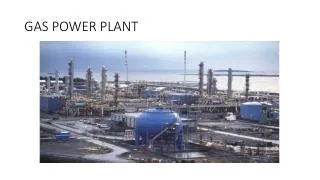
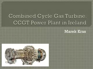
8-4 Brayton Cycle 8-4-1 The Equipments of Brayton Cycle
Advantages Gas turbine engines have a great power-to-weight ratio compared to reciprocating engines. That is, the amount of power you get out of the engine compared to the weight of the engine itself is very good. Gas turbine engines are smaller than their reciprocating counterparts of the same power
p T 2 Constant pressure 3 3 adiabatic 4 2 4 1 1 v s 8-4-2 Brayton Cycle
T 3’ Tmax 3 4 2 4’ 1 s 8-4-3 The Optimum Compression Ratio If T3 is limited: the compression ratio will be increased to get high efficiency But the power ratio will decrease
T Tmax T0 s We have to compromise between high efficiency and high power ratio. Usually in aerospace field the power ratio is more important Obviously there must be an optimum compression ratio which makes the cycle has maximum power ratio
This ratio is denoted as:εmax The efficiency depends on T3 basically
T T2 T1 T2 T1 s 8-4-4 The methods to increase the efficiency (1) Regenerative Brayton Cycle
Engine Characteristic Type Twin-Spool, Augmented Turbofan Application F-22 Advanced Tactical Fighter Thrust 35,000 Pound Thrust Class Engine Control Full-Authority Digital Electronic Control Compression System Twin Spool/Counter Rotating/Axial Flow/Low-Aspect Ratio Three-Stage Fan Six-Stage Compressor Combustor Annular Turbine Axial Flow/Counter Rotating• One-Stage, High-Pressure Turbine• One-Stage, Low-Pressure Turbine Nozzle Two-dimensional Vectoring Convergent/Divergent
Combustion chamber oil regenerator Air in gas turbine compressor
T s (2) Isothermal compression and regenerative cycle
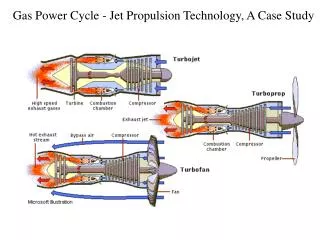
8-5 Jet Engine Engine Characteristic Type Twin-Spool, Augmented Turbofan Application F-22 Advanced Tactical Fighter Thrust 35,000 Pound Thrust Class Engine Control Full-Authority Digital Electronic Control Compression System Twin Spool/Counter Rotating/Axial Flow/Low-Aspect Ratio Three-Stage Fan Six-Stage Compressor Combustor Annular Turbine Axial Flow/Counter Rotating• One-Stage, High-Pressure Turbine• One-Stage, Low-Pressure Turbine Nozzle Two-dimensional Vectoring Convergent/Divergent
4 5 6 T 3 2 1 s 2 3 4 5 6 1
After burner The methods to increase the power ratio of jet engine (1) After burning
T s 6 4 7 5 3 2 1
T 4’ 5’ 4 6’ 6 3 2 1 s (2) Increase T4
8-5 The Stirling Cycle p T 3 4 3 2 4 2 1 1 v s
The End Of This Chapter Thank You