Download
1 / 11
170 likes | 642 Views
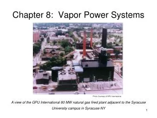
Chapter 8: Vapor Power Systems. Photo Courtesy of GPU International. A view of the GPU International 80 MW natural gas fired plant adjacent to the Syracuse University campus in Syracuse NY. Components of a Vapor Power Plant. Rankine Cycle. Pump:. Turbine:. Overall Performance:.

E N D
Chapter 8: Vapor Power Systems Photo Courtesy of GPU International A view of the GPU International 80 MW natural gas fired plant adjacent to the Syracuse University campus in Syracuse NY
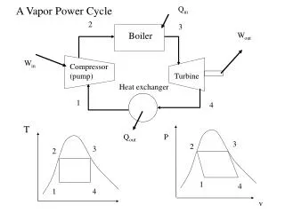
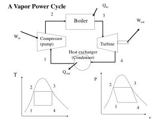
Rankine Cycle Pump: Turbine: Overall Performance: Condenser (1 side): Boiler:
Rankine Idealizations Processes 1-2, 3-4: Isentropic Processes 2-3, 4-1: Isobaric Saturated liquid at State 3 Reversible Pump Work Equation: For Incompressible Fluids Only!
Improving Cycle Performance One key is in the pressures: Each method increases cycle thermal efficiency!
Improving Cycle Performance Superheat and Reheat protect the turbine, and increase TH.
Improving Cycle Performance Adding an Open Feedwater Heater (with pump).
Improving Cycle Performance Adding a Closed Feedwater Heater.